


DMA Controller Module
MCF52211 ColdFire® Integrated Microcontroller Reference Manual, Rev. 2
17-8 Freescale Semiconductor
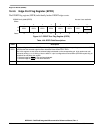
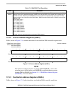
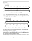
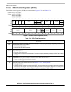
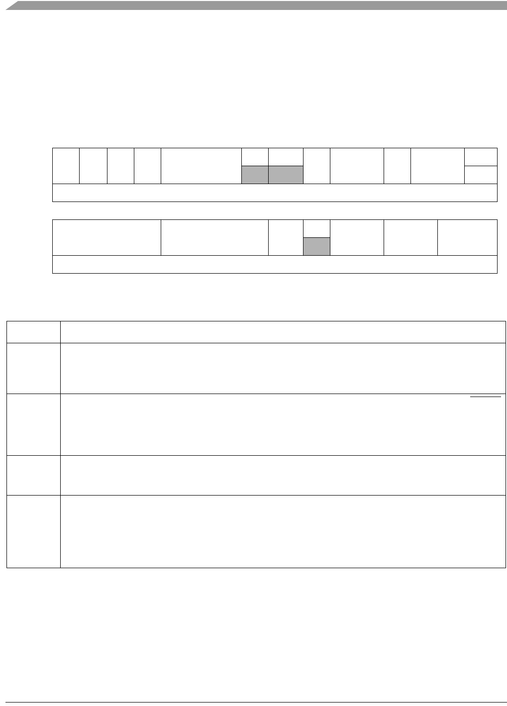
17.3.5 DMA Control Registers (DCRn)
The DMA control registers (DCRn) are described in Figure 17-8 and Table 17-4.
IPSBAR
Offsets:
0x00_010C (DCR0)
0x00_011C (DCR1)
0x00_012C (DCR2)
0x00_013C (DCR3)
31 30 29 28 27 26 25 24 23 22 21 20 19 18 17 16
R
INT EEXT CS AA BWC
00
SINC SSIZE DINC DSIZE
0
W START
Reset00000000 0 000000 0
15141312111098 7 654321 0
R
SMOD DMOD D_REQ
0
LINKCC LCH1 LCH2
W
Reset00000000 0 000000 0
Figure 17-8. DMA Control Registers (DCRn)
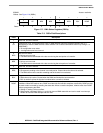
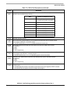
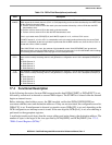
Table 17-4. DCRn Field Descriptions
Field Description
31
INT
Interrupt on completion of transfer. Determines whether an interrupt is generated by completing a transfer or by
the occurrence of an error condition.
0 No interrupt is generated.
1 Internal interrupt signal is enabled.
30
EEXT
Enable external request. Care should be taken because a collision can occur between the START bit and DREQ
n
when EEXT equals 1.
0 External request is ignored.
1 Enables external request to initiate transfer. The internal request (initiated by setting the START bit) is always
enabled.
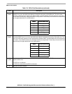
29
CS
Cycle steal.
0 DMA continuously makes read/write transfers until the BCR decrements to 0.
1 Forces a single read/write transfer per request.
28
AA
Auto-align. AA and SIZE determine whether the source or destination is auto-aligned, that is, transfers are
optimized based on the address and size. See Section 17.4.4.1, “Auto-Alignment.”
0 Auto-align disabled
1 If SSIZE indicates a transfer no smaller than DSIZE, source accesses are auto-aligned; otherwise, destination
accesses are auto-aligned. Source alignment takes precedence over destination alignment. If auto-alignment
is enabled, the appropriate address register increments, regardless of DINC or SINC.