


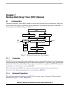

Backup Watchdog Timer (BWT) Module
MCF52211 ColdFire® Integrated Microcontroller Reference Manual, Rev. 2
Freescale Semiconductor 7-3
7.2.2 Register Descriptions
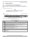
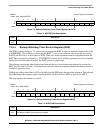
7.2.2.1 Backup Watchdog Timer Control Register (WCR)
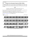
The WCR, shown in Figure 7-2, configures the operation of the BWT. It is a read-always/write-once
register; after the register is written, the contents cannot be changed until the next Power-On Reset event
occurs.
This register must be written as a whole.
NOTE
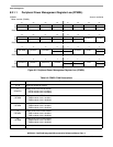
To ensure that the BWT is properly enabled, the software must write a value
to the WMR (see Section 7.2.2.2, “Backup Watchdog Timer Modulus
Register (WMR)”) prior to writing to the WCR.
IPSBAR
Offset: 0x14_0000 (WCR)
Access: Supervisor read/write
1514131211109876543210
R 0 0 0 0 0 000000
STOP
WAIT DOZE
1
EN
W
Reset
1
1
After Power-On Reset; the register contents are preserved during warm resets.
0000000000000010
Figure 7-2. Backup Watchdog Timer Control Register (WCR)
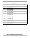
Table 7-2. WCR Field Descriptions
Field Description
15–5 Reserved, should read 0. Writes have no effect and terminate without transfer error exception.
4
STOP
Stop Mode bit. This read-always/write-once bit controls the function of the BWT in Stop mode.
0 BWT continues to operate when the device enters Stop mode as long as the BWT is provided with a clock.
1 BWT stops when the device enters Stop mode.
3
WAIT
Wait Mode bit. This read-always/write-once bit controls the function of the BWT in Wait mode.
0 BWT continues to operate when the device enters Wait mode.
1 BWT stops when the device enters Wait mode.
2
DOZE
Doze Mode bit. This read-always/write-once bit controls the function of the BWT in Doze mode.
0 BWT continues to operate when the device enters Doze mode.
1 BWT stops when the device enters Doze mode.
1 Reserved, should read 1.
0
EN
BWT Enable bit. This read-always/write-once bit enables the BWT.
0 BWT is disabled.
1 BWT is enabled.