


Power Management
MCF52211 ColdFire® Integrated Microcontroller Reference Manual, Rev. 2
8-10 Freescale Semiconductor
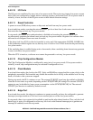
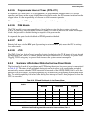
the cycle with an error termination. At reset, the IPSBMT is enabled with a maximum timeout value. See
Figure 8-7 and Table 8-9 for the IPSBMT definition.
8.4 Functional Description
The functions and characteristics of the low-power modes, and how each module is affected by, or affects
these modes are discussed in this section.
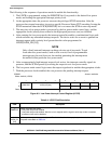
8.4.1 Low-Power Modes
The system enters a low-power mode by executing a STOP instruction. Which mode the device actually
enters (stop, wait, or doze) depends on what is programmed in LPCR[LPMD]. Entry into any of these
modes idles the CPU with no cycles active, powers down the system and stops all internal clocks
appropriately. During stop mode, the system clock is stopped low.
For entry into stop mode, the LPICR[ENBSTOP] bit must be set before a STOP instruction is issued.
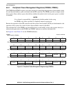
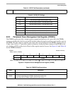
IPSBAR
Offset: 0x0023 (IPSBMT)
Access: read/write
31 30 29 28 27 26 25 24 23 22 21 20 19 18 17 16
R 0 0 0 0 0 0000 0 000 000
W
Reset000000000 0 0000 0 0
15 14 13 12 11 10 9 8 7 6 5 4 3 2 1 0
R 0 00000000 0 00
BME BMT
W
Reset000000000 0 0010 0 0
Figure 8-7. IPS Bus Timeout Monitor (IPSBMT) Register
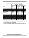
Table 8-9. IPSBMT Field Description
Field Description
15–4 Reserved, should be cleared.
3
BME
Bus Timeout Monitor Enable
0 The bus timeout monitor is disabled.
1 The bus timeout monitor is enabled.
2–0
BMT[2:0]
Bus Monitor Timeout. This field selects the timeout period (measured in system bus clock cycles) for the bus
monitor.
000 1024 cycles
001 512 cycles
010 256 cycles
011 128 cycles
100 64 cycles
101 32 cycles
110 16 cycles
111 8 cycles