LSI Specification
MB86617A
Rev.1.0 Fujitsu VLSI
17
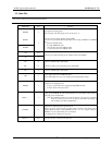
5.5. Other Pins
This section explains the pin function like internal PLL.
Signal Name I/O Function
XRESET I
Input signal for resetting signal
When operating with cable supply power, set this pin to ‘L’.
MODE1
MODE0
I
This pin is used for setting operating mode of MPU.
This device is operated as follows depending on the setting of MODE1 and MODE0
pins;
‘00’ input: TX1940 mode
‘01’ input: MB90F574 mode
‘10’ input: 80 system non-multiplex mode
‘11’ input: 68 system non-multiplex mode
XO I/O
XI I
Exterior type crystal connecting pin for oscillator circuit (24.576MHz)
RF O
Connect t o GND through 5.1kΩ register.
FIL O Exterior type filter circuit connecting pin for internal PLL
RO O Connect to GND through 5.1kΩ register.
CPS I
Power supply input pin from IEEE1394 cable
Detect cable supply power 0 to 33V (requiring of lowering/dividing voltage)
PMODE I
Criterion pin for inputting power
‘L’ input : operate with power supplying through IEEE1394 cable
‘H’ input: operate with system power
PWR3 - 1 I
Setting pin got POWER_CLASS of Self-ID packet to be transmitted when operating
with supply power through cable.
Note) The POWER_CLASS of the Self_ID packet to be sent when operating
under the system power does not use this pin, but follows the setting of
Pwr bit (Bit2 to 0) of Physical Register#4.
LINKON O
Output pin for detecting Link-on packet receive
Output ‘H’ when receiving Link-on packet under operating with supply power
through IEEE1394 cable. When PMODE becomes ‘H’, ‘L’ is output. With the
PMODE in ‘H’, the output of this pin is not changed.
If not using this pin, set this pin as open one.
TEST1 - 7 I/O This pin is for test. Use this pin as open one.


