


LSI Specification
MB86617A
Rev.1.0 Fujitsu VLSI
84
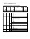
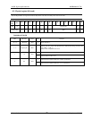
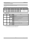
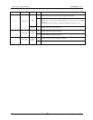
8.3. Physical register #01 (read/write)
Physical Register#01 is the register that set s/indicates force-root and gap-count.
Do not write into this register except for the case that the node is Bus manager or Isochronous resource manager in the environment with
no Bus manager.
phy/
link-
addr
R/W
Bit
15
Bit
14
Bit
13
Bit
12
Bit
11
Bit
10
Bit
9
Bit
8
Bit
7
Bit
6
Bit
5
Bit
4
Bit
3
Bit
2
Bit
1
Bit
0
02 h R/W - - - - - - - - RHB IRB Gap_count
Initial Value ‘0’ ‘0’ ‘0’ ‘0’ ‘0’ ‘0’ ‘0’ ‘0’ ‘0’’ ‘0’ “3F h”
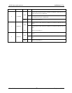
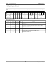
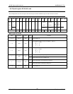
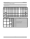
Description of Each Bit
BIT Bit Name Action Value Function
Read - Always indicate ‘0’.
15 - 8 reserved
Write - Always write ‘0’.
0 This node does not try to be root during next bus reset.
7
RHB
Note 1)
Read/
Write
1 This node tries to be root during next bus reset.
0 Does not perform bus reset.
6 IRB
Read/
Write
1 Performs bus reset. Automatically clears to “0” at the completion of bus reset.
Read - Indicate current gap-count value (MSB: 5 , LSB: 0).
5 - 0
Gap_count
Note 2)
Write - Set gap-count value (MSB: 5 , LSB: 0).
Note 1) This bit is automatically set by receiving the PHY configuration packet, too.
Note 2) This bit is automatically set by receiving the PHY configuration packet, too.
Also, this bit value returns to initial value at the second next bus reset.