LSI Specification
MB86617A
Rev.1.0 Fujitsu VLSI
63
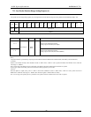
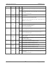
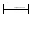
BIT Bit Name Action Value Function
0
Indicates that the data length of received packet is same as specified data length in
format.
10 Rx dlen-err-A Read
1
Indicates that the data length of received packet differs to the specified data length
in the format.
Clears to ‘0’ by lead of this register.
9 reserved Read - Always indicates ‘0’.
0 Indicates that transmit packet is transmitted normally.
8 Tx late-A Read
1
Indicates that transmit packet became Late packet. Delete packet, and not
transmit.
Clears to ‘0’ by lead of this register.
0 Indicates that the received packet is normal.
7 Rx late-A Read
1
Indicates that received packet was Late packet.
Delete packet, and not output to TSP-IC.
Clears to ‘0’ by lead of this register.
0 Indicates that 50/60 range of CIP header for received Isochronous packet is ‘0’.
6 Rx 56 err-A Read
1
Indicates that 50/60 range of CIP header of received Isochronous packet is ‘1’
Clears to ‘0’ by lead of this register.
0
Indicates that STYPE range of CIP hea der of received Isochronous packet is
‘00000’ or ‘00001’.
5
Rx stype
err-A
Read
1
Indicates that STYPE range of CIP header of received Isochronous packet is other
than ‘00000’ or ‘00001’.
Clears to ‘0’ by lead of this register.
0 Indicates that FIFO on LINK I/F side of bridge-Ach is not full.
4
BRG FIFO
full-A
Read
1 Indicates that FIFO on LINK I/F side of bridge-Ach is full.
0 Indicates that FIFO on LINK I/F side of bridge-Ach is not empty.
3
BRG FIFO
emp-A
Read
1 Indicates that FIFO on LINK I/F side of bridge-Ach is empty.
0 Indicates that DBC range of CIP header of received Isochronous packet is normal.
2 Rx DBC err-A Read
1
Indicates that DBC range of CIP header of received Isochronous packet received is
not consecutive.
Clears to ‘0’ by lead of this register.


