


1-5
Setting Up the Analyzer
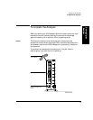
To Unpack the Analyzer
1 Setting Up the
Analyzer
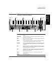
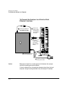
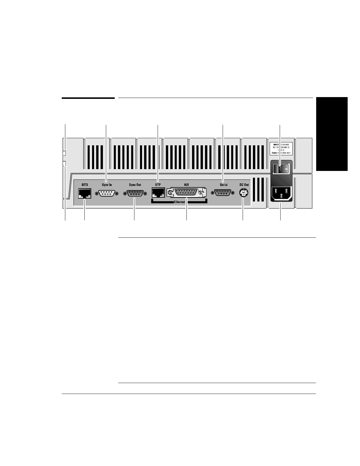
Connector Panel at a Glance
Power LED Light emitting diode (LED) that indicates when power is supplied to the
analyzer.
Access LED Light emitting Diode (LED) that indicates when the analyzer is accessing
information from a network.
BITS Input for synchronizing the analyzer to a Building Integrated Timing Source
(BITS) or to a DS1 or E1 source.
Sync In Input for synchronizing the analyzer’s Data Clocks, Measurement System,
or Data Timestamp to external equipment or another analyzer.
Sync Out Output for synchronizing external equipment, or for synchronizing the Data
Clocks, Measurement System, or Data Timestamps of another analyzer to
this analyzer.
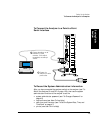
UTP Connects the analyzer to a 10BaseT (Ethertwist/TPE) Local Area Network.
When the analyzer is supplied with an Omnibook, the UTP port is used for
connecting the analyzer to the Omnibook.
AUI Attachment Unit Interface connector used with an external MAU (Medium
Attachment Unit) to allow connection of the analyzer to a variety of
different Local Area Networks.
Serial Port for connecting the analyzer to a Terminal using RS-232C serial
communications.
DC Out This output is not active.
BITS
Sync Out
Serial
AUI
(LAN)
DC Out
Sync In
UTP
(LAN)
Power
Outlet
Power On/Off
Switch
Power LED
Access
LED