


1-1
CHAPTER 1
GUIDE TO THIS MANUAL
This document is a supplement to the 8XC196NT Microcontroller User’s Manual. It describes
the differences between the 87C196CB and the 8XC196NT. For information not found in this
supplement, please consult the 8XC196NT Microcontroller User’s Manual (order number
272317) or the 87C196CB datasheet (87C196CA/87C196CB 20 MHz Advanced 16-Bit CHMOS
Microcontroller with Integrated CAN 2.0, order number 272405).
1.1 MANUAL CONTENTS
This supplement contains several chapters, an appendix, a glossary, and an index. This chapter,
Chapter 1, provides an overview of the supplement. This section summarizes the contents of the
remaining chapters and appendixes. The remainder of this chapter provides references to related
documentation.
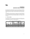
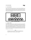
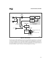
Chapter 2 — Architectural Overview — compares the features of the 87C196CB with those of
the 8XC196NT and describes the 87C196CB’s internal clock circuitry.
Chapter 3 — Memory Partitions — describes the addressable memory space of the 84-pin and
100-pin 87C196CB, lists the peripheral special-function registers (SFRs), and provides tables of
WSR values for windowing higher memory into the lower register file for direct access.
Chapter 4 — Standard and PTS Interrupts — describes the additional interrupts for the CAN
(controller area network) peripheral and the SFRs that support those interrupts.
Chapter 5 — I/O Ports — describes the port 0 and EPORT differences for the 100-pin
87C196CB. Both port 0 and the EPORT are implemented as eight-bit ports on the 100-pin
87C196CB, but as four-bit ports (like the 8XC196NT) on the 84-pin 87C196CB.
Chapter 6 — Analog-to-digital (A/D) Converter — illustrates the SFRs that are affected by the
implementation of port 0 as an eight-bit port.
Chapter 7 — CAN Serial Communications Controller — describes the 87C196CB’s integrat-
ed CAN controller and explains how to configure it. This integrated peripheral is similar to Intel’s
standalone 82527 CAN serial communications controller, supporting both the standard and ex-
tended message frames specified by the CAN 2.0 protocol parts A and B.
Chapter 8 — Special Operating Modes — illustrates the clock control circuitry of the
87C196CB.