


87C196CB Supplement
A-12
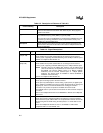
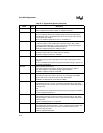
SD1:0 I/O Data Pins for SSIO0 and 1
SD0 is multiplexed with P6.5, and SD1 is multiplexed with P6.7.
SLP7:0 I/O Slave Port Address/Data bus
Slave port address/data bus in multiplexed mode and slave port data bus in
demultiplexed mode. In multiplexed mode, SLP1 is the source of the internal
control signal, SLP_ADDR.
SLP7:0 are multiplexed with AD7:0, P3.7:0, and PBUS.7:0.
SLPALE I Slave Port Address Latch Enable
Functions as either a latch enable input to latch the value on SLP1 (with a
multiplexed address/data bus) or as the source of the internal control signal,
SLP_ADDR (with a demultiplexed address/data bus).
SLPALE is multiplexed with P5.0, ADV#, and ALE.
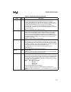
SLPCS# I Slave Port Chip Select
SLPCS# must be held low to enable slave port operation.
SLPCS# is multiplexed with P5.1 and INST.
SLPINT O Slave Port Interrupt
This active-high slave port output signal can be used to interrupt the master
processor.
SLPINT is multiplexed with P5.4 and a special test-mode-entry pin . See P5.7:0
for special considerations.
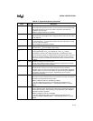
SLPRD# I Slave Port Read Control Input
This active-low signal is an input to the slave. Data from the P3_REG or
SLP_STAT register is valid after the falling edge of SLPRD#.
SLPRD# is multiplexed with P5.3 and RD#.
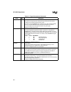
SLPWR# I Slave Port Write Control Input
This active-low signal is an input to the slave. The rising edge of SLPWR#
latches data on port 3 into the P3_PIN or SLP_CMD register.
SLPWR# is multiplexed with P5.2, WR#, and WRL#.
T1CLK I Timer 1 External Clock
External clock for timer 1. Timer 1 increments (or decrements) on both rising
and falling edges of T1CLK. Also used in conjunction with T1DIR for quadrature
counting mode.
and
External clock for the serial I/O baud-rate generator input (program selectable).
T1CLK is multiplexed with P6.2.
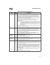
T2CLK I Timer 2 External Clock
External clock for timer 2. Timer 2 increments (or decrements) on both rising
and falling edges of T2CLK. Also used in conjunction with T2DIR for quadrature
counting mode.
T2CLK is multiplexed with P1.0 and EPA0.
T1DIR I Timer 1 External Direction
External direction (up/down) for timer 1. Timer 1 increments when T1DIR is high
and decrements when it is low. Also used in conjunction with T1CLK for
quadrature counting mode.
T1DIR is multiplexed with P6.3.
Table A-3. Signal Descriptions (Continued)
Name Type Description