


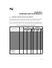


87C196CB SUPPLEMENT
4-2
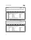
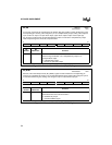
INT_MASK1
Address:
Reset State:
0013H
00H
The interrupt mask 1 (INT_MASK1) register enables or disables (masks) individual interrupt requests.
(The EI and DI instructions enable and disable servicing of all maskable interrupts.) INT_MASK1 can
be read from or written to as a byte register. PUSHA saves this register on the stack and POPA
restores it.
7 0
NMI EXTINT CAN RI TI SSIO1 SSIO0 CBF
7:0 Setting a bit enables the corresponding interrupt.
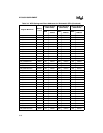
The standard interrupt vector locations are as follows:
Bit Mnemonic Interrupt Standard Vector
NMI
†
Nonmaskable Interrupt FF203EH
EXTINT EXTINT Pin FF203CH
CAN CAN Peripheral FF203AH
RI SIO Receive FF2038H
TI SIO Transmit FF2036H
SSIO1 SSIO 1 Transfer FF2034H
SSIO0 SSIO 0 Transfer FF2032H
CBF Slave Port Command Buffer Full FF2030H
†
NMI is always enabled. This nonfunctional mask bit exists for design symmetry with the
INT_PEND1 register. Always write zero to this bit.
Figure 4-1. Interrupt Mask 1 (INT_MASK1) Register
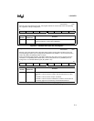
INT_PEND1
Address:
Reset State:
0012H
00H
When hardware detects a pending interrupt, it sets the corresponding bit in the interrupt pending
(INT_PEND or INT_PEND1) registers. When the vector is taken, the hardware clears the pending bit.
Software can generate an interrupt by setting the corresponding interrupt pending bit.
7 0
NMI EXTINT CAN RI TI SSIO1 SSIO0 CBF
7:0 Any set bit indicates that the corresponding interrupt is pending. The interrupt bit is cleared
when processing transfers to the corresponding interrupt vector.
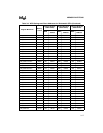
The standard interrupt vector locations are as follows:
Bit Mnemonic Interrupt Standard Vector
NMI Nonmaskable Interrupt FF203EH
EXTINT EXTINT Pin FF203CH
CAN
†
CAN Peripheral FF203AH
RI SIO Receive FF2038H
TI SIO Transmit FF2036H
SSIO1 SSIO 1 Transfer FF2034H
SSIO0 SSIO 0 Transfer FF2032H
CBF Slave Port Command Buffer Full FF2030H
Figure 4-2. interrupt Pending 1 (INT_PEND1) Register