


7-29
CAN SERIAL COMMUNICATIONS CONTROLLER
7.6 ENABLING THE CAN INTERRUPTS
The CAN controller has a single interrupt input (INT13) to the interrupt controller. (Generally,
PTS interrupt service is not useful for the CAN controller because the PTS cannot readily deter-
mine the source of the CAN controller’s multiplexed interrupts.) To enable the CAN controller’s
interrupts, you must enable the interrupt source by setting the CAN bit in INT_MASK1 (see Ta-
ble 7-2 on page 7-3) and globally enable interrupt servicing (by executing the EI instruction). In
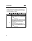
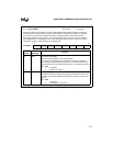
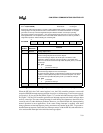
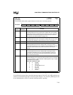
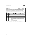
addition, you must set bits in the CAN control register (Figure 7-17) and the individual message
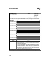
objects’ control register 0 (Figure 7-18) to enable the individual interrupt sources within the CAN
controller.
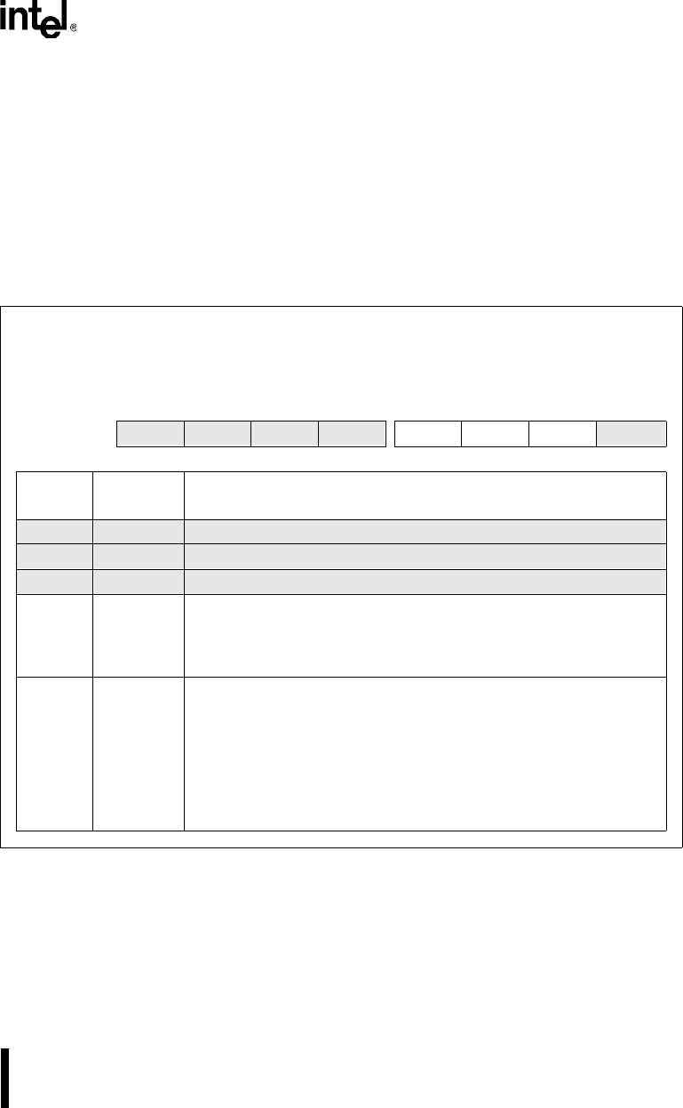
CAN_CON
(87C196CB)
Address:
Reset State:
1E00H
01H
Program the CAN control (CAN_CON) register to control write access to the bit timing registers, to
enable and disable CAN interrupts, and to control access to the CAN bus.
7 0
87C196CB
— CCE — — EIE SIE IE INIT
Bit
Number
Bit
Mnemonic
Function
7 — Reserved; for compatibility with future devices, write zero to this bit.
6 CCE Change Configuration Enable
5:4 — Reserved; for compatibility with future devices, write zeros to these bits.
3 EIE Error Interrupt Enable
This bit enables and disables the bus-off and warn interrupts.
0 = disable bus-off and warn interrupts
1 = enable bus-off and warn interrupts
2 SIE Status-change Interrupt Enable
This bit enables and disables the successful reception (RXOK), successful
transmission (TXOK), and error code change (LEC2:0) interrupts.
0 = disable status-change interrupt
1 = enable status-change interrupt
When the SIE bit is set, the CAN controller generates a successful
reception (RXOK) interrupt request each time it receives a valid message,
even if no message object accepts it.
Figure 7-17. CAN Control (CAN_CON) Register