


87C196CB Supplement
A-8
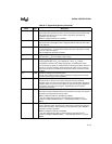
HLDA# O Bus Hold Acknowledge
This active-low output indicates that the CPU has released the bus as the result
of an external device asserting HOLD#.
HLDA# is multiplexed with P2.6 and CPVER.
HOLD# I Bus Hold Request
An external device uses this active-low input signal to request control of the
bus. This pin functions as HOLD# only if the pin is configured for its special
function and the bus-hold protocol is enabled. Setting bit 7 of the window
selection register (WSR) enables the bus-hold protocol.
HOLD# is multiplexed with P2.5.
INST O Instruction Fetch
This active-high output signal is valid only during external memory bus cycles.
When high, INST indicates that an instruction is being fetched from external
memory. The signal remains high during the entire bus cycle of an external
instruction fetch. INST is low for data accesses, including interrupt vector
fetches and chip configuration byte reads. INST is low during internal memory
fetches.
INST is multiplexed with P5.1 and SLPCS#.
INTOUT# O Interrupt Output
This active-low output indicates that a pending interrupt requires use of the
external bus. How quickly the microcontroller asserts INTOUT# depends upon
the status of HOLD# and HLDA# and whether the microcontroller is executing
from internal or external program memory. If the microcontroller is executing
from internal memory and receives an interrupt request while in hold, it asserts
INTOUT# immediately. However, if the microcontroller is executing code from
external memory and receives an interrupt request while in hold, it asserts
BREQ# and waits until the external device deasserts HOLD# to assert
INTOUT#. If the microcontroller is executing code from external memory and
receives an interrupt request as it is going into hold (between the time that an
external device asserts HOLD# and the time that the microcontroller responds
with HLDA#), the microcontroller asserts both HLDA# and INTOUT# and keeps
them asserted until the external device deasserts HOLD#.
INTOUT is multiplexed with P2.4 and AINC#.
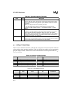
NMI I Nonmaskable Interrupt
In normal operating mode, a rising edge on NMI generates a nonmaskable
interrupt. NMI has the highest priority of all prioritized interrupts. Assert NMI for
greater than one state time to guarantee that it is recognized.
ONCE# I On-circuit Emulation
Holding ONCE# low during the rising edge of RESET# places the device into
on-circuit emulation (ONCE) mode. This mode puts all pins into a high-
impedance state, thereby isolating the device from other components in the
system. The value of ONCE# is latched when the RESET# pin goes inactive.
While the device is in ONCE mode, you can debug the system using a clip-on
emulator. To exit ONCE mode, reset the device by pulling the RESET# signal
low. To prevent inadvertent entry into ONCE mode, either configure this pin as
an output or hold it high during reset and ensure that your system meets the V
IH
specification (see datasheet).
ONCE# is multiplexed with P2.6.
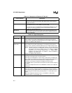
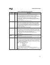
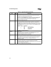
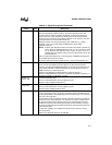
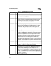
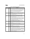
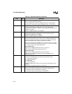
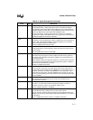
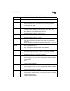
Table A-3. Signal Descriptions (Continued)
Name Type Description