


7-11
CAN SERIAL COMMUNICATIONS CONTROLLER
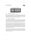
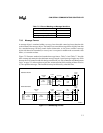
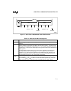
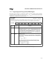
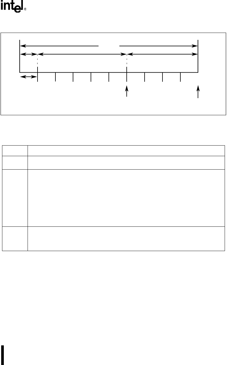
Figure 7-5. A Bit Time as Implemented in the CAN Controller
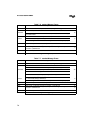
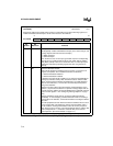
Table 7-9. CAN Controller Bit Time Segments
Symbol Definition
t
SYNC_SEG
This time segment is equivalent to SYNC_SEG in the CAN protocol. Its length is one time
quantum.
t
TSEG1
This time segment is equivalent to the sum of PROP_SEG and PHASE_SEG1 in the CAN
protocol. Its length is specified by the TSEG1 field in bit timing register 1. To allow for resyn-
chronization, the sample point can be moved (t
TSEG
1
or t
TSEG
2
can be shortened and the other
lengthened) by 1 to 4 time quanta, depending on the programmed value of the SJW field in bit
timing register 0.
The CAN controller samples the bus once or three times, depending on the value of the
sampling mode (SPL) bit in bit timing register 0. In three-sample mode, the hardware
lengthens t
TSEG
1
by 2 time quanta to allow time for the additional two bus samples. In this
case, the “sample point” shown in Figure 7-5 is the time of the third sample; the first and
second samples occur 2 and 1 time quanta earlier, respectively.
t
TSEG2
This time segment is equivalent to PHASE_SEG2 in the CAN protocol. Its length is specified
by the TSEG2 field in bit timing register 1. To allow for resynchronization, the sample point
can be moved (t
TSEG
1
or t
TSEG
2
can be shortened and the other lengthened) by 1 to 4 time
quanta, depending on the programmed value of the SJW field in bit timing register 0.
TSEG1
Sample Transmit
1 tq
Bit Time
(TSEG1 + 1)tq
t
A2602-01
TSEG2
t
SYNC
_SEG
t
(TSEG2 + 1)tq