


7-13
CAN SERIAL COMMUNICATIONS CONTROLLER
7.4 CONFIGURING THE CAN CONTROLLER
This section explains how to configure the CAN controller. Several registers combine to control
the configuration: the CAN control register, the two bit timing registers, and the three mask reg-
isters.
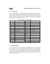
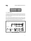
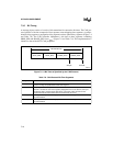
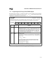
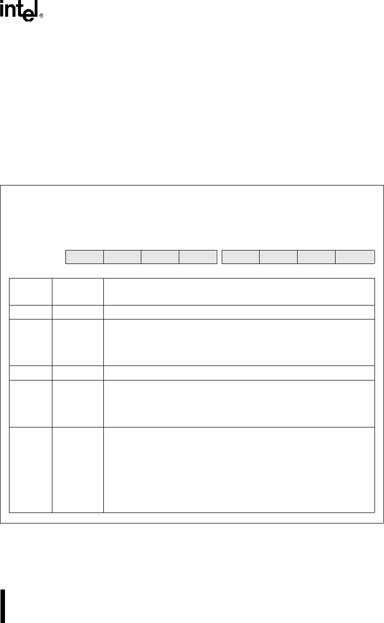
7.4.1 Programming the CAN Control (CAN_CON) Register
The CAN control register (Figure 7-6) controls write access to the bit timing registers, enables
and disables global interrupt sources (error, status change, and individual message object), and
controls access to the CAN bus.
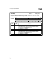
CAN_CON
(87C196CB)
Address:
Reset State:
1E00H
01H
Program the CAN control (CAN_CON) register to control write access to the bit timing registers, to
enable and disable CAN interrupts, and to control access to the CAN bus.
7 0
87C196CB
— CCE — — EIE SIE IE INIT
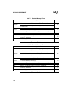
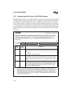
Bit
Number
Bit
Mnemonic
Function
7 — Reserved; for compatibility with future devices, write zero to this bit.
6 CCE Change Configuration Enable
This bit controls whether software can write to the bit timing registers.
0 = prohibit write access
1 = allow write access
5:4 — Reserved; for compatibility with future devices, write zeros to these bits.
3 EIE Error Interrupt Enable
This bit enables and disables the bus-off and warn interrupts.
0 = disable bus-off and warn interrupts
1 = enable bus-off and warn interrupts
2 SIE Status-change Interrupt Enable
This bit enables and disables the successful reception (RXOK), successful
transmission (TXOK), and error code change (LEC2:0) interrupts.
0 = disable status-change interrupt
1 = enable status-change interrupt
When the SIE bit is set, the CAN controller generates a successful
reception (RXOK) interrupt request each time it receives a valid message,
even if no message object accepts it.
Figure 7-6. CAN Control (CAN_CON) Register