


7-33
CAN SERIAL COMMUNICATIONS CONTROLLER
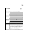
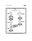
If an individual message object caused the interrupt request (CAN_INT = 02–10H), software can
read the associated message object control 0 register (Figure 7-21). The INT_PND bit-pair will
be set, indicating that a receive or transmit interrupt request is pending
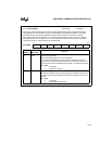
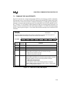
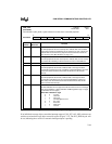
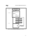
CAN_STAT
(87C196CB)
Address:
Reset State:
1E01H
XXH
The CAN status (CAN_STAT) register reflects the current status of the CAN peripheral.
7 0
87C196CB
BUSOFF WARN — RXOK TXOK LEC2 LEC1 LEC0
Bit
Number
Bit
Mnemonic
Function
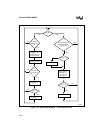
7 BUSOFF Bus-off Status
The CAN peripheral sets this read-only bit to indicate that it has isolated
itself from the CAN bus (floated the TX pin) because an error counter has
reached 256. A bus-off recovery sequence clears this bit and clears the
error counters. (See “Bus-off State” on page 7-41.)
6 WARN Warning Status
The CAN peripheral sets this read-only bit to indicate that an error counter
has reached 96, indicating an abnormal rate of errors on the CAN bus.
5 — Reserved. This bit is undefined.
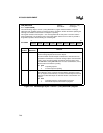
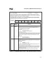
4 RXOK Reception Successful
The CAN peripheral sets this bit to indicate that a message has been
successfully received (error free, regardless of acknowledgment) since the
bit was last cleared. Software must clear this bit when it services the
interrupt.
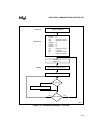
3 TXOK Transmission Successful
The CAN peripheral sets this bit to indicate that a message has been
successfully transmitted (error free and acknowledged by at least one
other node) since the bit was last cleared. Software must clear this bit
when it services the interrupt.
2:0 LEC2:0 Last Error Code
This field indicates the error type of the first error that occurs in a message
frame on the CAN bus. (“Error Detection and Management Logic” on page
7-9 describes the error types.)
LEC2 LEC1 LEC0 Error Type
0 0 0 no error
001stuff error
0 1 0 form error
0 1 1 acknowledgment error
1 0 0 bit 1 error
1 0 1 bit 0 error
1 1 0 CRC error
1 1 1 unused
Figure 7-20. CAN Status (CAN_STAT) Register