


87C196CB SUPPLEMENT
7-4
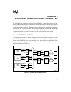
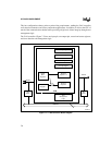
7.3 CAN CONTROLLER OPERATION
This section describes the address map, message objects, message frames (which contain mes-
sage objects), error detection and management logic, and bit timing for CAN transmissions and
receptions.
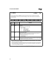
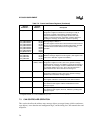
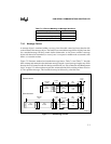
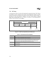
CAN_MSG
x
CON1 1E
y
1H Message Object
x
Control 1
Program this register to indicate that a message is ready to
transmit or to initiate a transmission. Read this register to
determine whether the message object contains new data,
whether a message has been overwritten, whether software is
updating the message, and whether a transfer is pending.
CAN_MSG
x
DATA0
CAN_MSG
x
DATA1
CAN_MSG
x
DATA2
CAN_MSG
x
DATA3
CAN_MSG
x
DATA4
CAN_MSG
x
DATA5
CAN_MSG
x
DATA6
CAN_MSG
x
DATA7
1E
y7
H
1E
y
8H
1E
y
9H
1E
y
AH
1E
y
BH
1E
y
CH
1E
y
DH
1E
y
EH
Message Object
x
Data 0–7
The data registers contain data to be transmitted or data received.
Do not use unused data bytes as scratch-pad memory; the CAN
controller writes random values to these registers during
operation.
CAN_MSG
x
ID0
CAN_MSG
x
ID1
CAN_MSG
x
ID2
CAN_MSG
x
ID3
1E
y
2H
1E
y
3H
1E
y
4H
1E
y
5H
Message Object
x
Identification 0–3
Write the message object’s ID to this register. (This register is the
same as the arbitration register of the 82527.)
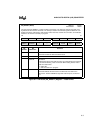
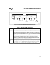
CAN_MSK15 1E0CH, 1E0DH,
1E0EH, 1E0FH
Message 15 Mask
Program this register to mask (“don’t care”) specific message
identifier bits for message 15 in addition to those bits masked by a
global mask. The message 15 mask is ANDed with the standard
or extended global mask, so any “don’t care” bits defined in a
global mask are also “don’t care” bits for message 15.
CAN_SGMSK 1E06H, 1E07H Standard Global Mask
Program this register to mask (“don’t care”) specific message
identifier bits for standard message objects.
CAN_STAT 1E01H Status
This register reflects the current status of the CAN controller.
INT_MASK1 0013H Interrupt Mask 1
The CAN bit in this register enables and disables the CAN
interrupt request.
INT_PEND1 0012H Interrupt Pending 1
The CAN bit in this register, when set, indicates a pending CAN
interrupt request.
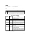
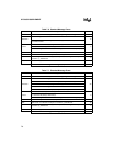
Table 7-2. Control and Status Registers (Continued)
Register
Mnemonic
††
Register
Address
††
Description
†
The CCE bit in CAN_CON must be set to enable write access to the bit timing registers.
††
In register names,
x
= 1–15; in addresses,
y
= 1–F.