


A-7
SIGNAL DESCRIPTIONS
EA# I External Access
This input determines whether memory accesses to special-purpose and
program memory partitions (FF2000–FF9FFFH) are directed to internal or
external memory. These accesses are directed to internal memory if EA# is
held high and to external memory if EA# is held low. For an access to any other
memory location, the value of EA# is irrelevant.
EA# also controls entry into programming mode. If EA# is at V
PP
voltage
(typically +12.5 V) on the rising edge of RESET#, the device enters
programming mode.
NOTE: Systems with EA# tied inactive have idle time between external bus
cycles. When the address/data bus is idle, you can use ports 3 and 4
for I/O. Systems with EA# tied active cannot use ports 3 and 4 as
standard I/O; when EA# is active, these ports will function only as the
address/data bus.
EA# is sampled and latched only on the rising edge of RESET#. Changing the
level of EA# after reset has no effect.
On devices with no internal nonvolatile memory, always connect EA# to V
SS
.
EPA9:0 I/O Event Processor Array (EPA) Input/Output pins
These are the high-speed input/output pins for the EPA capture/compare
channels. For high-speed PWM applications, the outputs of two EPA channels
(either EPA0 and EPA1 or EPA2 and EPA3) can be remapped to produce a
PWM waveform on a shared output pin.
EPA9:0 are multiplexed as follows: EPA0/P1.0/T2CLK, EPA1/P1.1,
EPA2/P1.2/T2DIR, EPA3/P1.3, EPA4/P1.4, EPA5/P1.5, EPA6/P1.6, EPA7/P1.7,
EPA8/P6.0/COMP0, and EPA9/P6.1/COMP1.
EPORT.7:0
(100-pin CB)
I/O Extended Addressing Port
This is a 4-bit, bidirectional, memory-mapped I/O port.
EPORT.7:0 are multiplexed with A23:16.
EPORT.3:0
(84-pin CB)
I/O Extended Addressing Port
This is a 4-bit, bidirectional, memory-mapped I/O port.
EPORT.3:0 are multiplexed with A19:16.
EXTINT I External Interrupt
In normal operating mode, a rising edge on EXTINT sets the EXTINT interrupt
pending bit. EXTINT is sampled during phase 2 (CLKOUT high). The minimum
high time is one state time.
In powerdown mode, asserting the EXTINT signal for at least 50 ns causes the
device to resume normal operation. The interrupt need not be enabled, but the
pin must be configured as a special-function input. If the EXTINT interrupt is
enabled, the CPU executes the interrupt service routine. Otherwise, the CPU
executes the instruction that immediately follows the command that invoked the
power-saving mode.
In idle mode, asserting any enabled interrupt causes the device to resume
normal operation.
EXTINT is multiplexed with P2.2 and PROG#.
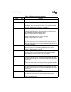
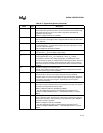
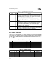
Table A-3. Signal Descriptions (Continued)
Name Type Description