


7-35
CAN SERIAL COMMUNICATIONS CONTROLLER
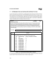
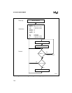
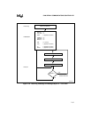
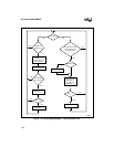
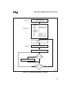
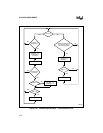
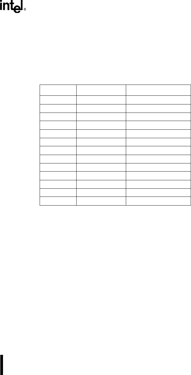
7.8 FLOW DIAGRAMS
The flow diagrams in this section describe the steps that your software (shown as CPU) and the
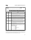
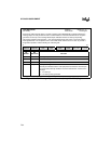
CAN controller execute to receive and transmit messages. Table 7-13 lists the register bits shown
in the diagrams along with their associated registers and a cross-reference to the figure that de-
scribes them.
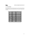
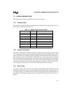
Table 7-13. Cross-reference for Register Bits Shown in Flowcharts
Bit Mnemonic Register Mnemonic Figure and Page
CPUUPD CAN_MSG
x
CON1 Figure 7-15 on page 7-26
DIR CAN_MSG
x
CFG Figure 7-12 on page 7-21
DLC CAN_MSG
x
CFG Figure 7-12 on page 7-21
ID CAN_MSG
x
ID Figure 7-13 on page 7-22
INT_PND CAN_MSG
x
CON0 Figure 7-14 on page 7-24
MSGLST CAN_MSG
x
CON1 Figure 7-15 on page 7-26
MSGVAL CAN_MSG
x
CON0 Figure 7-14 on page 7-24
NEWDAT CAN_MSG
x
CON1 Figure 7-15 on page 7-26
RMTPND CAN_MSG
x
CON1 Figure 7-15 on page 7-26
RXIE CAN_MSG
x
CON0 Figure 7-14 on page 7-24
TXIE CAN_MSGxCON0 Figure 7-14 on page 7-24
TX_REG CAN_MSG
x
CON1 Figure 7-15 on page 7-26
XTD CAN_MSG
x
CFG Figure 7-12 on page 7-21