


6-1
CHAPTER 6
ANALOG-TO-DIGITAL (A/D) CONVERTER
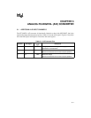
6.1 ADDITIONAL A/D INPUT CHANNELS
The 87C196CB’s A/D converter is functionally identical to that of the 8XC196NT, but it has
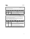
eight analog input channels instead of four. Table 6-1 lists the A/D signals. Figure 6-1 describes
the command register and Figure 6-2 describes the result register.
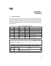
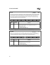
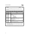
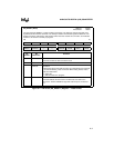
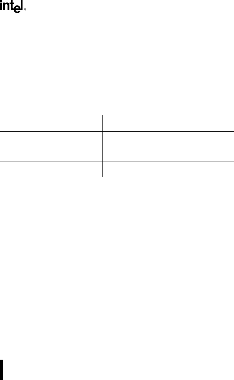
Table 6-1. A/D Converter Pins
Port Pin A/D Signal
A/D Signal
Type
Description
P0.7:0 ACH7:0 I Analog inputs. See the “Voltage on Analog Input Pin”
specification in the datasheet.
— ANGND GND Reference Ground
Must be connected for A/D converter and port operation.
—V
REF
PWR Reference Voltage
Must be connected for A/D converter and port operation.