


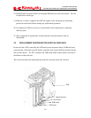
D SERIES CONTROLLER
TROUBLESHOOTING AND COMPONENT REPLACEMENT
2-8
K
a
a
aw
s
k
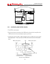
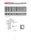
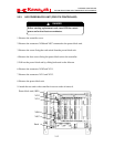
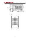
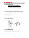
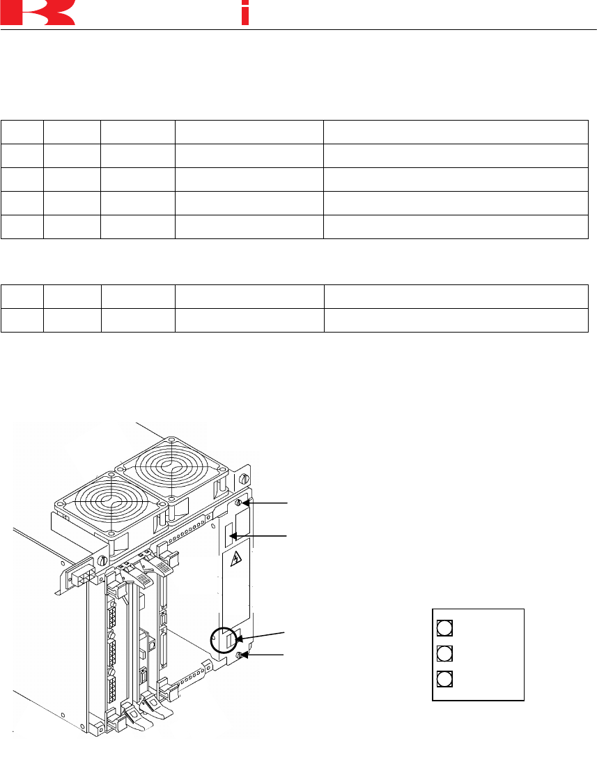
6. Confirm the voltage at each check pin on the 1KA and 1KP as shown below.
1KA board
No. Color Standard Allowable range If the voltage is out of allowable range,
TP2 Yellow
−12.0 V −11.95 V∼ −12.05 V
Adjust the volume on the AVR.
TP3 Yellow +12.0 V
+11.95 V∼ +12.05 V
Adjust the volume on the AVR.
TP4 Yellow +5.0 V
+4.95 V∼ +5.05 V
Adjust the volume on the AVR.
TP6 Yellow +3.3 V
+3.16 V∼ +3.44 V
Replace the 1KA.
1KP board
No. Color Standard Allowable range If the voltage is out of allowable range,
TP1 White +24.0 V
+23.9 V∼ +24.7 V
Replace the AVR.
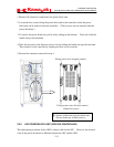
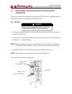
7. If there is no abnormality in the controller after checking voltage, paint lock each adjust
volume of the AVR.
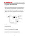
Vo l u m e
(enlarged view)
+5V Adjust
+12V Adjust
−12V Adjust
Screw
Screw
Connector
Vo l u m e
Overview of the AV
R