


D SERIES CONTROLLER
TROUBLESHOOTING AND COMPONENT REPLACEMENT
2-15
K
a
a
aw
s
k
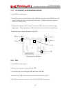
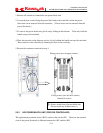
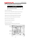
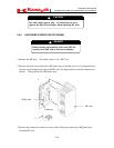
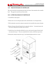
2.4 REPLACEMENT PROCEDURE FOR MC UNIT PARTS (FOR D3X
CONTROLLER)
This section describes the replacement procedure for the MC unit (power supply unit) and the
1KQ board (power circuit board) which flanks the MC unit.
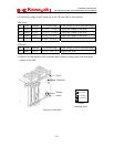
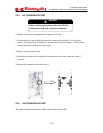
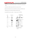
2.4.1 MC UNIT
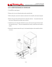
1. To facilitate the replacement process, remove all connectors and power block connectors
connected to the MC unit.
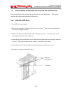
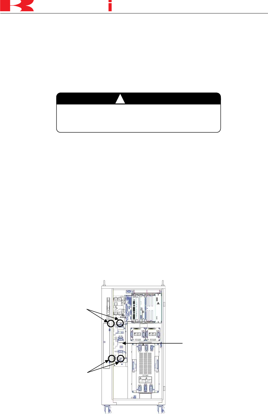
2. Loosen the four screws fixing the MC unit to the controller, then remove the MC unit from
the controller.* (See figure below.)
NOTE* Fully removing the screws may cause the MC unit to drop, or make the restoration
process unnecessarily difficult. Be sure to leave the screws on the controller side.
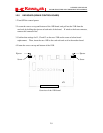
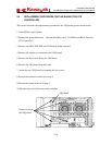
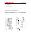
3. Attach the new MC unit to the controller, and fasten it with the four screws.**
NOTE** Be careful not to let the washers/screws fall under the MC unit.
4. Restore the connectors removed in step 1.
Fixing screws
(two in upper corners)
Fixing screws
(two in lower corners)
MC unit
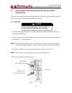
DANGER
!
Before starting replacement work, turn OFF the
control
p
ower and wait at least seven minutes.