


145
CHAPTER 3 SPECIFICATIONS
3
3.4 Buffer Memory Assignment
3.4.2 Details of the buffer memory
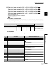
(65)CH Sensor two-point correction gain latch completion (Un\G551, Un\G583,
Un\G615, Un\G647)
When sensor two-point correction gain value is stored, 1 is stored in this buffer memory area, which is Latch
completed (1).
When CH Sensor two-point correction gain latch request (Un\G550, Un\G582, Un\G614, Un\G646) is set to No
request (0), 0 is stored in this buffer memory area, which is No request (0). ( Page 144, Section 3.4.2 (64))
For details on the sensor two-point correction function, refer to the following.
Page 213, Section 4.14 (2)
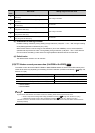
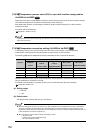
(66)During AT loop disconnection detection function enable/disable setting
(Un\G571)
Set whether to enable or disable the loop disconnection detection function during auto tuning.
For details on the during AT loop disconnection detection function, refer to the following.
Page 255, Section 4.23
(a) Setting range
• 0: Disable
• 1: Enable
(b) Default value
The default values are set to Disable (0) in all channels.
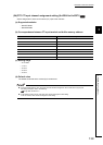
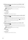
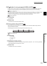
(67)CH AT simultaneous temperature rise parameter calculation flag (Un\G573,
Un\G605, Un\G637, Un\G669)
The status when simultaneous temperature rise AT (auto tuning) calculates simultaneous temperature rise
parameter is stored in this buffer memory area.
• 0: OFF
• 1: ON
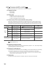
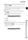
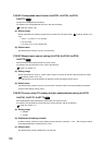
Common
Standard
b15 b3 b2 b1 b0
Bit data from b15 to b4 are fixed to 0.
to
000000000000
b4
CH4CH3CH2CH1
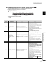
Standard
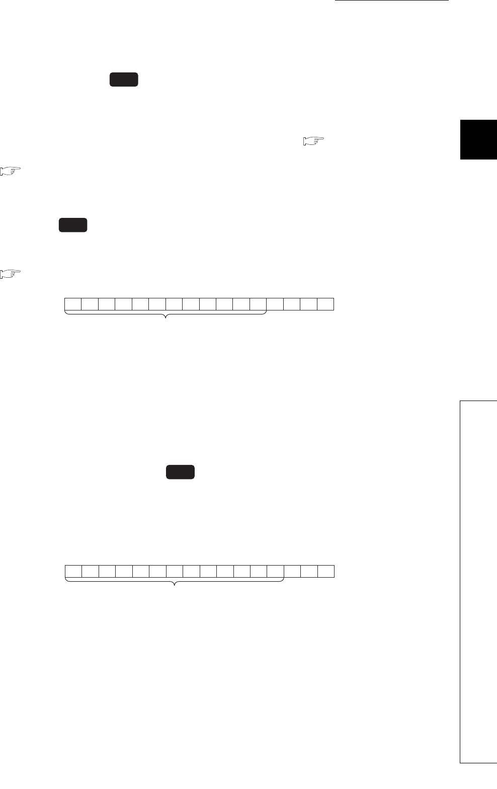
b15 b3 b2 b1 b0
Bit data from b15 to b3 are fixed to 0.
to
0000000000000