


321
CHAPTER 7 PROGRAMMING
7
7.2 When Using the Module in a Standard System Configuration
7.2.2 Standard control (peak current suppression function, simultaneous temperature rise function)
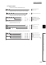
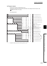
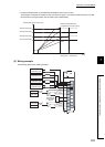
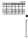
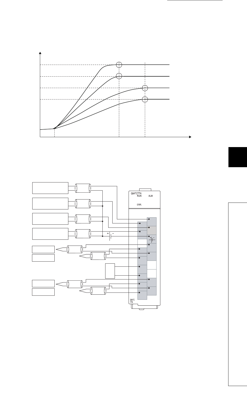
• Program example where the simultaneous temperature rise function is used
This program is designed to classify the CH1 and CH2 into group 1 and CH3 and CH4 into group 2 so that
the channels in each group reach the set values (SV) simultaneously.
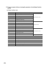
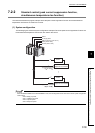
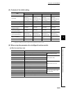
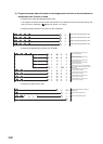
(3) Wiring example
The following figure shows a wiring example.
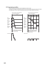
CH4 Set value (SV)
Matches temperature rise
completion time in each group
Temperature process value (PV)
Time
Group 1
arrival point
CH3 Set value (SV)
CH2 Set value (SV)
CH1 Set value (SV)
Temperature rise start
Group 2
arrival point
Heater CH3
Operation input
Heater CH4
Operation input
Cold junction
temperature
compensation
resistor
CH1 Input
CH2 Input
CH3 Input
CH4 Input
COM-
CJ
CJ
CH1 +
CH2 +
CH1 -
CH2 -
L1
L2
L3
L4
24VDC
CJ
CJ
NC
NC
IN3 3-
IN3 3+
NC
OUT1
OUT3
OUT4
IN1 1+
IN1 1-
IN2 2+
IN2 2-
IN4 4+
IN4 4-
OUT2
+
-
+
-
Heater CH2
Operation input
+
-
Heater CH1
Operation input
+
-
CH3 +
CH4 +
CH3 -
CH4 -