


15
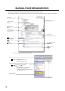
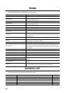
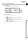
Pages describing buffer memory areas and functions are organized as shown below.
The following illustration is for explanation purpose only, and should not be referred to as an actual documentation.
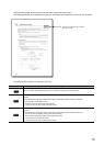
The following table describes the meaning of each icon.
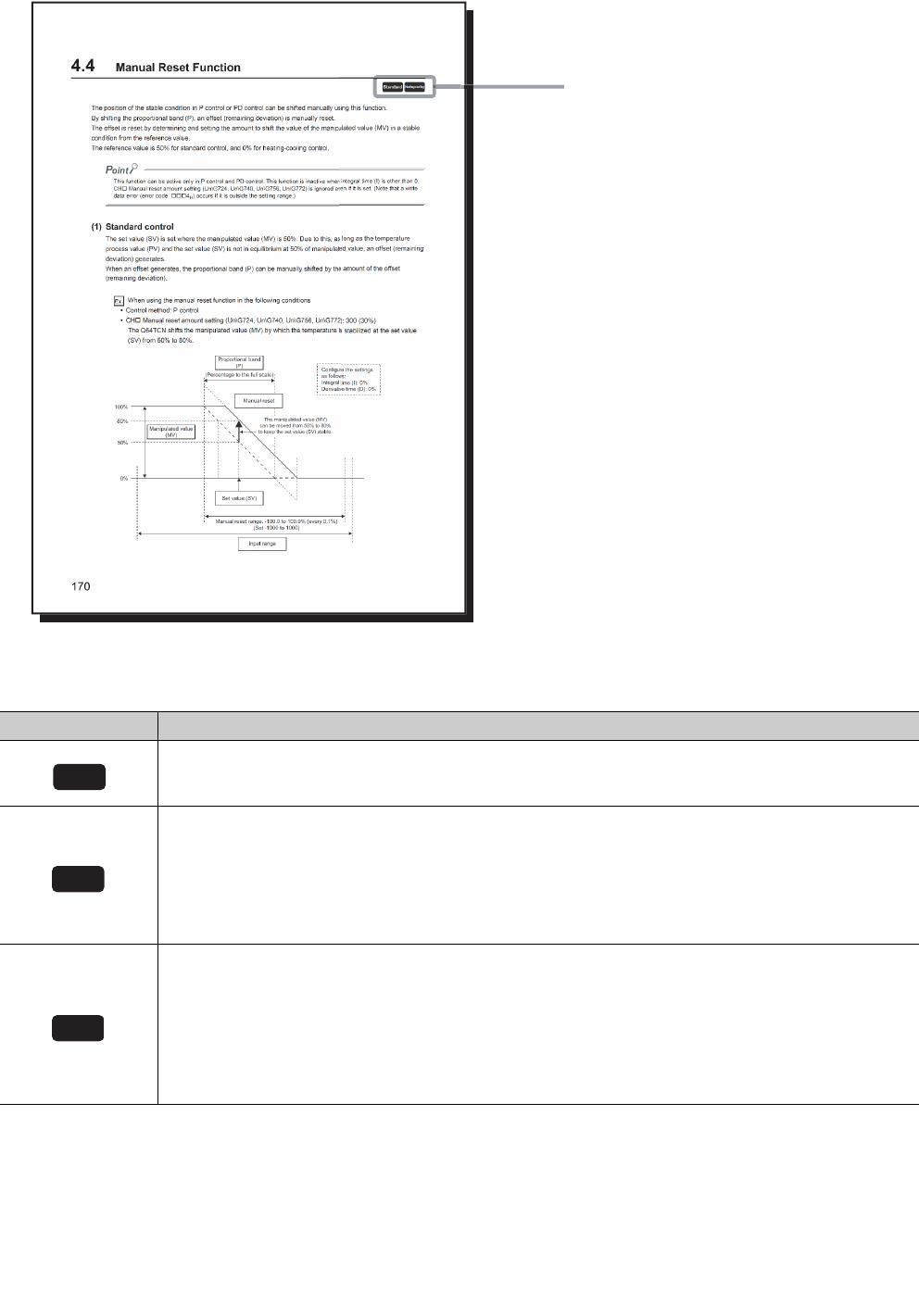
Icon Meaning
This icon means that the buffer memory area or function can be used in all control modes.
This icon means that the buffer memory area or function for temperature control can be used in the standard
control.
The buffer memory area and function can be used in the following control modes and channels:
• CH1 to CH4 in the standard control
• CH3 and CH4 in the mix control (normal mode)
• CH3 and CH4 in the mix control (expanded mode)
This icon means that the buffer memory or function for temperature control can be used in the heating-cooling
control.
The buffer memory area and function can be used in the following control modes and channels:
• CH1 and CH2 in the heating-cooling control (normal mode)
• CH1 to CH4 in the heating-cooling control (expanded mode)
• CH1 in the mix control (normal mode)
• CH1 and CH2 in the mix control (expanded mode)
These icons indicate control modes
that can be used.
Common
Standard
Heating-cooling