


310
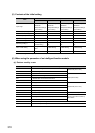
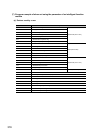
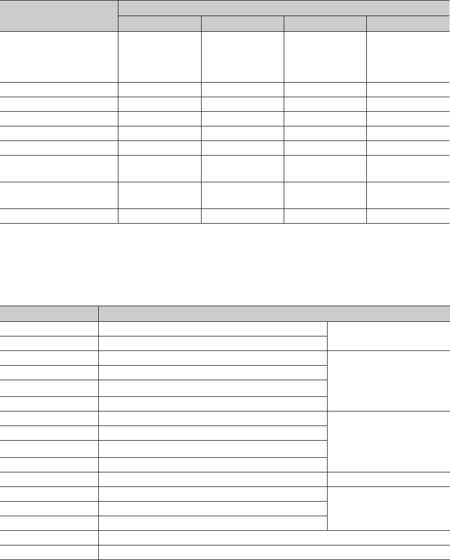
(5) Contents of the initial setting
*1 This setting is necessary only when the self-tuning function is used.
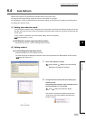
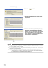
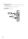
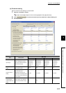
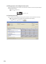
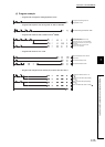
(6) When using the parameter of an intelligent function module
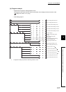
(a) Devices used by a user
Item
Description
CH1 CH2 CH3 CH4
Input range
2: Thermocouple K
Measured
Temperature Range
(0 to 1300°C)
2: Thermocouple K
Measured
Temperature Range
(0 to 1300°C)
2: Thermocouple K
Measured
Temperature Range
(0 to 1300°C)
2: Thermocouple K
Measured
Temperature Range
(0 to 1300°C)
Set value (SV) setting 200°C 0°C 0°C 0°C
Unused channel setting 0: Used 1: Unused 1: Unused 1: Unused
Control output cycle setting 30s 30s 30s 30s
Upper limit setting limiter 400°C 1300°C 1300°C 1300°C
Lower limit setting limiter 0°C 0°C 0°C 0°C
Self-tuning setting*1
1: Starting ST (PID
Constant Only)
0: Do Not Run the
ST
0: Do Not Run the
ST
0: Do Not Run the
ST
Alert 1 mode setting
1: Upper Limit Input
Alert
0: Not Warning 0: Not Warning 0: Not Warning
Alert set value 1 250°C 0°C 0°C 0°C
Device Description
X10 Module READY flag
Q64TCTTN (X10 to X1F)
X12 Write error flag
X22 Error code reset instruction
QX42 (X20 to X5F)
X23 Operation mode setting instruction
X24
E
2
PROM's PID constants read instruction
X30 CH1 Set value (SV) change instruction
Y11 Setting/operation mode instruction
Q64TCTTN (Y10 to Y1F)
Y12 Error reset instruction
Y18
E
2
PROM backup instruction
Y1B Setting change instruction
Y60 to Y6F Error code output QY42P (Y60 to Y9F)
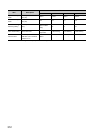
D50 Write data error code
Devices where data is written by
auto refresh
D51 CH1 Temperature process value (PV)
D55 CH1 Alert definition
M20 to M23 CH Read completion flag
M24 to M27 CH Write completion flag