


42
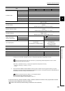
3.1.2 Sampling cycle and control output cycle
This section describes the sampling cycle and control output cycle of the Q64TCN.
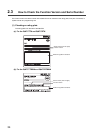
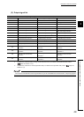
(1) Sampling cycle
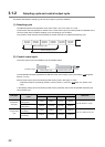
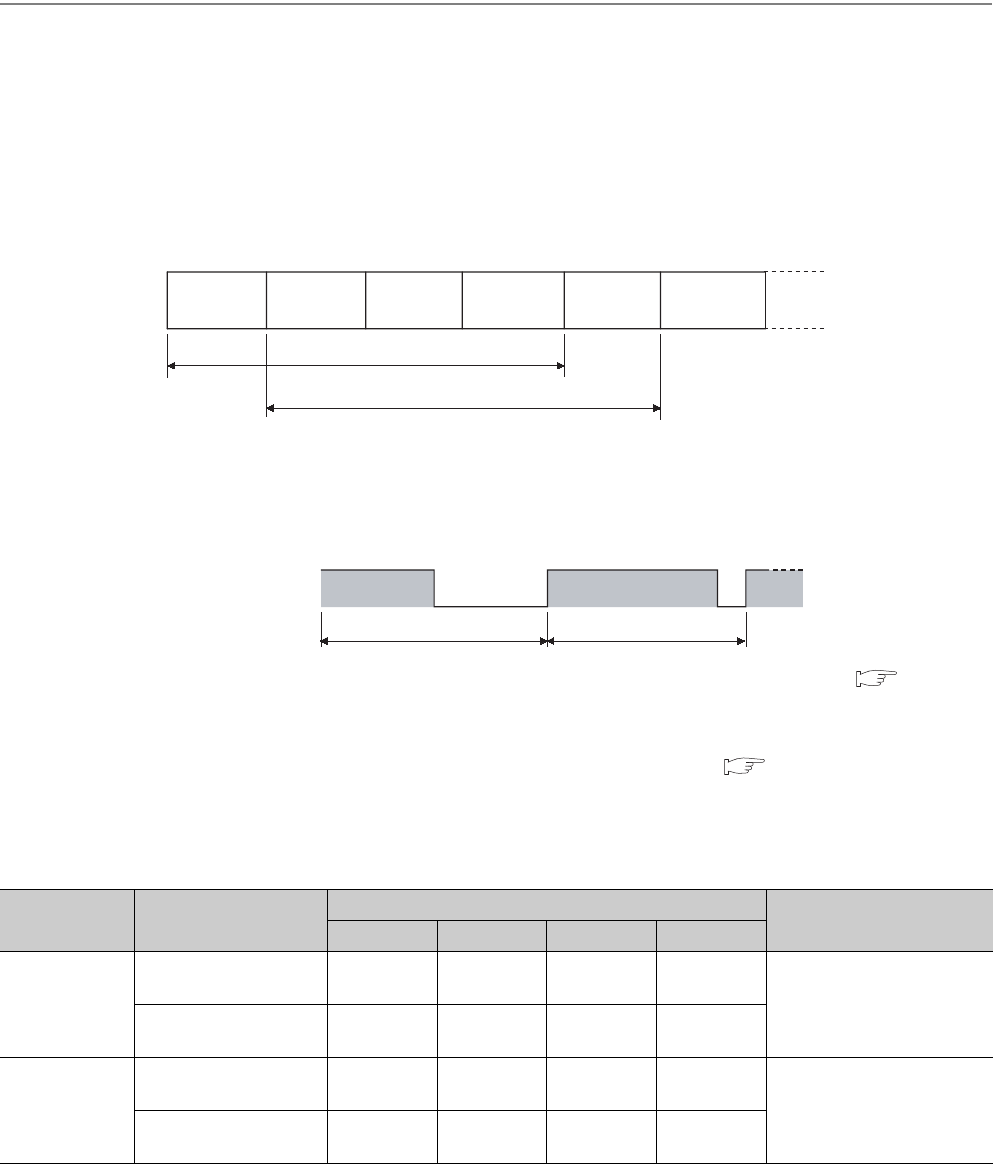
The Q64TCN performs PID operations in the order of CH1, CH2, CH3, CH4, CH1, CH2 .....
The time from when PID operation is started on the current channel (CHn) until PID operation is restarted on the
current channel (CHn) is called a sampling cycle. The sampling cycle is 500ms.
The number of used channels and the settings of unused channels do not affect the sampling cycle.
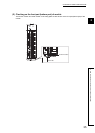
(2) Control output cycle
The control output cycle is the ON/OFF cycle of transistor output.
The manipulated value (MV) represents the ON time of the control output cycle in percentage. ( Page 89,
Section 3.4.2 (5))
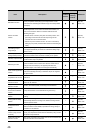
Set the control output cycle in the following buffer memory area in the range 1 to 100s.
•CH Control output cycle setting (Un\G47, Un\G79, Un\G111, Un\G143) ( Page 114, Section 3.4.2
(23))
In the heating-cooling control, the following buffer memory areas are used for the manipulated value (MV) and
control output cycle.
Data type
Buffer memory area
name
Buffer memory address
Reference
CH1 CH2 CH3 CH4
Manipulated
value (MV)
Manipulated value for
heating (MVh)
Un\G13 Un\G14 Un\G15 Un\G16
Page 89, Section 3.4.2 (5)
Manipulated value for
cooling (MVc)
Un\G704 Un\G705 Un\G706 Un\G707
Control output
cycle
Heating control output
cycle setting
Un\G47 Un\G79 Un\G111 Un\G143
Page 114, Section 3.4.2 (23)
Cooling control output
cycle setting
Un\G722 Un\G738 Un\G754 Un\G770
500ms (sampling cycle)
500ms (sampling cycle)
CH1 PID
operation
CH2 PID
operation
CH3 PID
operation
CH4 PID
operation
CH1 PID
operation
CH2 PID
operation
Transistor output
OFF
ON ON
OFF
Control output cycle Control output cycle