


82
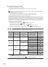
*1 This value is stored when Default setting registration instruction (Yn9) is turned on. The default value varies depending
on the mode. For details on the default values, refer to the following.
Page 86, Section 3.4.2
*2 This column indicates whether data can be read from or written to the buffer memory area through sequence programs.
R: Reading enabled
W: Writing enabled
*3 This column indicates whether the setting in the buffer memory area is automatically changed when the input range is
changed. Enable/disable of automatic change can be set on Switch Setting. For details, refer to Page 220, Section
4.15.
*4 Whether writing to the E
2
PROM by turning off and on E
2
PROM backup instruction (Yn8) is enabled is indicated in this
column. For details, refer to Page 270, Section 4.30.
*5 (TT) indicates the Q64TCTTN and Q64TCTTBWN. (RT) indicates the Q64TCRTN and Q64TCRTBWN.
*6 Available only when the heating-cooling control (expanded mode) is set on Switch Setting. With other models, this area
is handled as a system area.
*7 Available only when the mix control (expanded mode) is set on Switch Setting. With other models, this area is handled
as a system area.
*8 Available only when the Q64TCTTN or Q64TCTTBWN is used. With other models, this area is handled as a system
area.
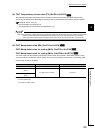
*9 Available only in the setting mode. To enable the setting contents, turn off, on, and on Setting change instruction (YnB)
when Setting/operation mode instruction (Yn1) is off (during setting mode). Note that a write data error (error code:
3
H
) occurs if the setting is changed during the operation mode.
*10 By using the setting change rate limiter, whether to set temperature rise/temperature drop in a batch or individually can
be selected on Switch Setting. In the batch setting, the target of setting change rate limiter is only this area. In the
individual setting, this area is the setting target for the temperature rise. For details, refer to Page 190, Section 4.9.
*11 Available only when the Q64TCTTBWN or Q64TCRTBWN is used. With other models, this area is handled as a system
area.
*12 By using the setting change rate limiter, whether to set temperature rise/temperature drop in a batch or individually can
be selected on Switch Setting. In the batch setting, this area is handled as a system area. In the individual setting, this
area is the setting target for the temperature drop. For details, refer to Page 190, Section 4.9.
*13 Available only when the heating-cooling control (normal mode) is set on Switch Setting. With other models, this area is
handled as a system area.
*14 Available only when the mix control (normal mode) is set on Switch Setting. With other models, this area is handled as a
system area.
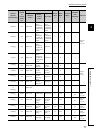
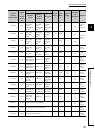
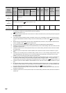
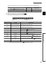
788(314
H
)
System area to
1278(4FE
H
)
1279(4FF
H
)
Buffer memory for error history ( Page 83, Section 3.4.1 (2))
to
4095(FFF
H
)
4096(1000
H
)
System area to
53247(CFFF
H
)
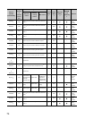
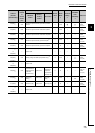
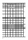
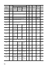
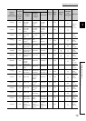
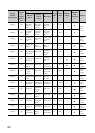
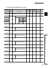
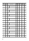
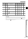
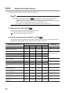
Address
(decimal
(hexadecimal))
Target
channel
or
current
sensor
(CT)
Setting contents
Default
value
*1
Read/
Write
*2
Automatic
setting
*3
E
2
PROM
write
availability
*4
Reference
Standard
control
Heating-
cooling
control
Mix control