


29
CHAPTER 2 SYSTEM CONFIGURATION
2
2.1 Applicable Systems
CHAPTER 2 SYSTEM CONFIGURATION
This chapter describes the system configuration of the Q64TCN.
2.1 Applicable Systems
This section describes applicable systems.
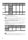
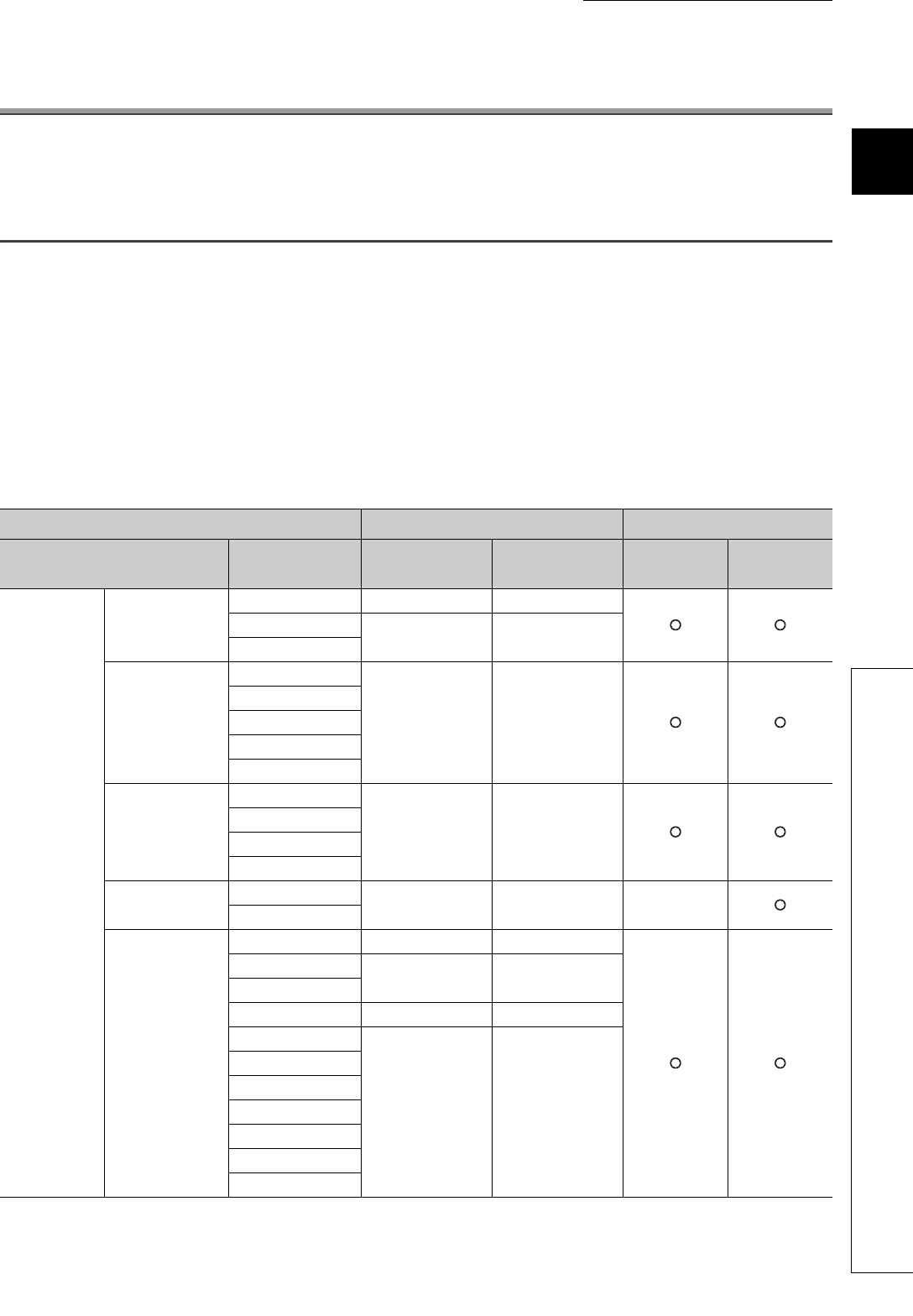
(1) Applicable CPU modules and base units, and number of mountable modules
The following table lists CPU modules and base units applicable to the Q64TCN and the number of mountable
Q64TCN.
Depending on the combination with other modules or the number of mounted modules, power supply capacity
may be insufficient.
Select the power supply capacity according to the module to be used. If the power supply capacity is insufficient,
change the combination of the modules.
Applicable CPU module
Number of modules
*1
Applicable base unit
*2
CPU type CPU model
Q64TCTTN/
Q64TCRTN
Q64TCTTBWN/
Q64TCRTBWN
Main base
unit
Extension
base unit
Programmable
controller CPU
Basic model
QCPU
Q00JCPU Up to 16 Up to 8
Q00CPU
Up to 24 Up to 12
Q01CPU
High Performance
model QCPU
Q02CPU
Up to 64 Up to 32
Q02HCPU
Q06HCPU
Q12HCPU
Q25HCPU
Process CPU
Q02PHCPU
Up to 64 Up to 32
Q06PHCPU
Q12PHCPU
Q25PHCPU
Redundant CPU
Q12PRHCPU
Up to 53 Up to 26 ×
Q25PRHCPU
Universal model
QCPU
Q00UJCPU Up to 16 Up to 8
Q00UCPU
Up to 24 Up to 12
Q01UCPU
Q02UCPU Up to 36 Up to 18
Q03UDCPU
Up to 64 Up to 32
Q04UDHCPU
Q06UDHCPU
Q10UDHCPU
Q13UDHCPU
Q20UDHCPU
Q26UDHCPU