


87
CHAPTER 3 SPECIFICATIONS
3
3.4 Buffer Memory Assignment
3.4.2 Details of the buffer memory
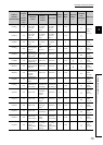
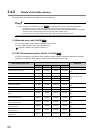
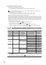
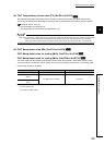
Stored values differ depending on the setting in CH Input range (Un\G32, Un\G64, Un\G96, Un\G128).
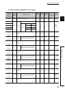
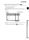
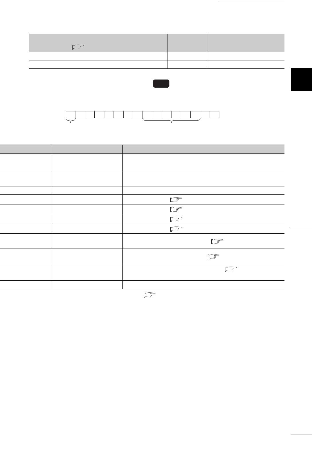
(3) CH Alert definition (Un\G5 to Un\G8)
Bits corresponding to alerts detected in each channel become 1.
*1 For the temperature measurement range, refer to Page 88, Section 3.4.2 (3) (a).
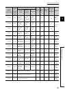
Setting of CH Input range (Un\G32, Un\G64, Un\G96,
Un\G128) ( Page 96, Section 3.4.2 (12))
Stored value Setting contents
Resolution is 1. 0 Nothing after decimal point
Resolution is 0.1. 1 First decimal place
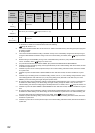
Target bit number Flag name Alert definition
b0 CH Input range upper limit
Temperature process value (PV) has exceeded the temperature
measurement range
*1
of the set input range.
b1 CH Input range lower limit
Temperature process value (PV) has fallen below the temperature
measurement range
*1
of the set input range.
b2 to b7 (fixed to 0) (Unused)
b8 CH Alert 1
Alert 1 has occurred. ( Page 194, Section 4.12)
b9 CH Alert 2
Alert 2 has occurred. ( Page 194, Section 4.12)
b10 CH Alert 3
Alert 3 has occurred. ( Page 194, Section 4.12)
b11 CH Alert 4
Alert 4 has occurred. ( Page 194, Section 4.12)
b12
CH Heater disconnection
detection
Heater disconnection has been detected. ( Page 265, Section 4.28)
b13
CH Loop disconnection
detection
Loop disconnection has been detected. ( Page 253, Section 4.22)
b14
CH Output off-time current
error
Output off-time current error has been detected. ( Page 269, Section
4.29)
b15 (fixed to 0) (Unused)
Common
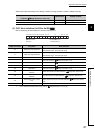
b15 b2 b1 b0
Bit data b15 are
fixed to 0.
Bit data from b7 to
b2 are fixed to 0.
b7b8b9b10b11b12b13b14
0 000000
to