Pacific Research Solutions RI-300e User Manual
Page 132
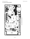
ANALOG CIRCUIT BOARD DESCRIPTION
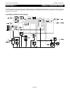
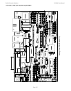
• The input of the RI-300 has an adjustable gain stage, U1-7. VR1 is used to set the gain of this stage.
• U2-8 is a low pass filter with a cutoff frequency of 4500 Hz. This filter is used to reduce adjacent channel splatter.
• The output of the low pass filter goes to U9 where a high pass filter is located with a cutoff frequency of 300 Hz. This
filter can be turned on/off and is used to remove the receiver CTCSS tones and DCS codes.
• The output of the U9 goes to the cross point switch and U5-1 a de-emphasis filter.
• U5-1 is a de-emphasis filter used primarily for the DTMF decoder and telephone audio.
• U2-7 is a low pass filter used to reject the voice band. The output of this filter feeds the CTCSS/DCS decoder.
• U9 is used for decoding CTCSS tones and shipping audio for decoding DCS codes by the processor.
• U9 is used to encode CTCSS tones. The output goes to U2-1 and then to a digital level control pot.
• U1-8 is the noise filter for the RI-300’s squelch circuit.
• The noise filter then goes to the U1-14, a gain stage used to adjust the squelch level. The output of the gain stage goes to
the cross point switch, U17.
• The cross point switches U17 and U18, can connect any of the Y inputs to any of the X outputs. This switch is the primary
method of all audio routing in the RI-300.
• The output of the Cross point switch goes to several places. The first is U5-8 a summing amplifier used to mix all audio
sources for the transmitter.
• The output of U5-8 feeds a digital potentiometer used to set the transmit modulation level.
• U7-7 is a buffer used to drive the repeater transmitter.
• Some of the audio in the controller will need pre-emphasis before the transmitter, U5-7. These audios include the
telephone, CTCSS/DCS, DTMF. Tone Generator and sometimes the AUX audio.
• The cross point switch is also used to control what audio goes to the U4-7 and U3-8 the AC to DC converter.
• The output of the AC to DC converter goes to an 8-bit analog to digital converter, U13. This converter allows the
microprocessor to read the squelch noise level, receiver audio level and the telephone audio level.
• U6-14 is a limiter used to limit the maximum audio level sent to the telephone line.
• U7-1 and U8-7 make up the hybrid for the telephone interconnect. The digital potentiometer in this circuit is controlled by
the microprocessor to balance the telephone hybrid.
• The output of the hybrid goes to U5-14 a gain stage also used as the telephone AGC. The digital potentiometer in this
circuit is controlled by the microprocessor where the AGC is controlled.
• The output of the telephone hybrid is coupled to the telephone line using T1.
• K1 is used as the hook switch and for pulse dialing.
• SP2 is a fast acting semi-conductor used for lighting protection. F1 and F2 are self-resetting fuses.
• U22 is an opto coupler used as a ring detector.
• U16 is an open collect output driver used to drive the hook relay, PTT and the user port output bits.
• U12 is the DTMF decoder and encoder.
• U10 is a dual tone generator and in-band tone decoder. This is used to generate the CW messages. Each tone generator
has it own digital level control pot.
• U3-7 is a buffer for the AUX audio output.
• U8 is a cross point switch for the AUX audio input.
• The output of U8 goes to a summing amplifier U3-1


