Pacific Research Solutions RI-300e User Manual
Page 75
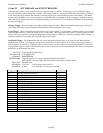
S-Cmd 45 LOGIC INPUTS and INTERNAL FUNCTIONS – STATE CHANGE TRIGGER
The controller has three digital inputs on board and is expandable to 10 inputs that can trigger macros. There are also an
additional 24 internal functions that also can trigger macros. Each of these inputs or functions can be configured to act on
either a negative or positive state change (falling and rising edges). When the controller detects any changes in these inputs or
functions, a macro starting at the “Macro Start Line” (1 through 999) will be executed. To disable an input or function, use 0 as
the Macro Start Line. See section 4 and 5 for information on the connector pin numbers for each input. This feature can be
used to generate an alarm message on change of an input state.
SYNTAX: 45 [Bit] [State] [Macro start line]
READ BACK: 45 [Bit] [State]
STORAGE: RAM/EEPROM
PARAMETERS: Bit 01 – 03 = On board inputs 1 – 3, Bit 09 – 15 = Optional input bits 9 – 15 (Sec. 2.14, RBI-3)
Bit 17 – 24 = Tone Remote decoder, Bit 25 = Repeater COS, Bit 26 = Repeater Tone Panel
Bit 27 = Repeater PTT, Bit 28 = AUX input COS, Bit 29 = AUX input Tone Panel
Bit 30 = AUX input PTT, Bit 31 = Local AUX Tone Panel, Bit 32 = Telephone Ring Detector
State 0 = Falling edge (High to Low), State 1 = Rising edge (Low to High)
Macro start line 0 = Disable, 1 – 999 = Macro start lines
DEFAULT: All bits set to 0
EXAMPLE: 45 01 0 10 Input #1 Falling edge triggers macro starting at line 10.
45 27 0 11 Repeater PTT Falling edge triggers macro starting at line 11.
45 01 1 12 Input #1 Rising edge triggers macro starting at line 12.
45 27 1 344 Repeater PTT Rising edge triggers macro starting at line 344.
S-Cmd 46 DIGITAL LOGIC OUTPUT, ON / OFF
The controller has three digital outputs on board and is expandable to 10 outputs. Each of these outputs can be directly turned
on or off with this command. See section 4 and 5 for information on the pin numbers for each output. This function can be
used to turn on something external to the controller.
SYNTAX: 46 [Output] [Mode]
READ BACK: 46 [Output]
STORAGE: RAM (Return to default at power on reset)
PARAMETERS: Output 01-03 = On board outputs
Output 04-16 = Optional (RBI-3 and VXR-5000 interface board)
Mode 0 = off, 1 = on
DEFAULT: All outputs are off when power is turned on (Logic high)
EXAMPLE: 46 01 1 Turns output number 1 on
S-Cmd 47 DIGITAL LOGIC OUTPUT PULSED ON FOR X TIME
The controller has three digital outputs on board that can be pulsed on for a programmed time duration. A pulsed output will go
high for the programmed time, and then low again. The pulse time is programmed in tenths of seconds. See section 4 and 5 for
information on the pin numbers for each output. This function can be used to turn on something external to the controller for a
set time.
SYNTAX: 47 [Output] [Pulse time]
READ BACK: 47 [Output]
STORAGE: RAM (Return to default at power on reset)
PARAMETERS: Output Bit 1-3 = On board digital output. Optional: Bit 10-16 (Sec. 2.14)
Pulse time 0-65000 (6500.0 Seconds) = Time the output goes logic high in tenths of seconds
DEFAULT: All 0
EXAMPLE: 47 1 65 Pulses output number 1 high for 6.5 Seconds.


