Pacific Research Solutions RI-300e User Manual
Page 133
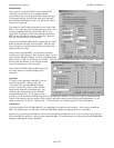
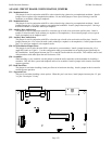
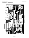
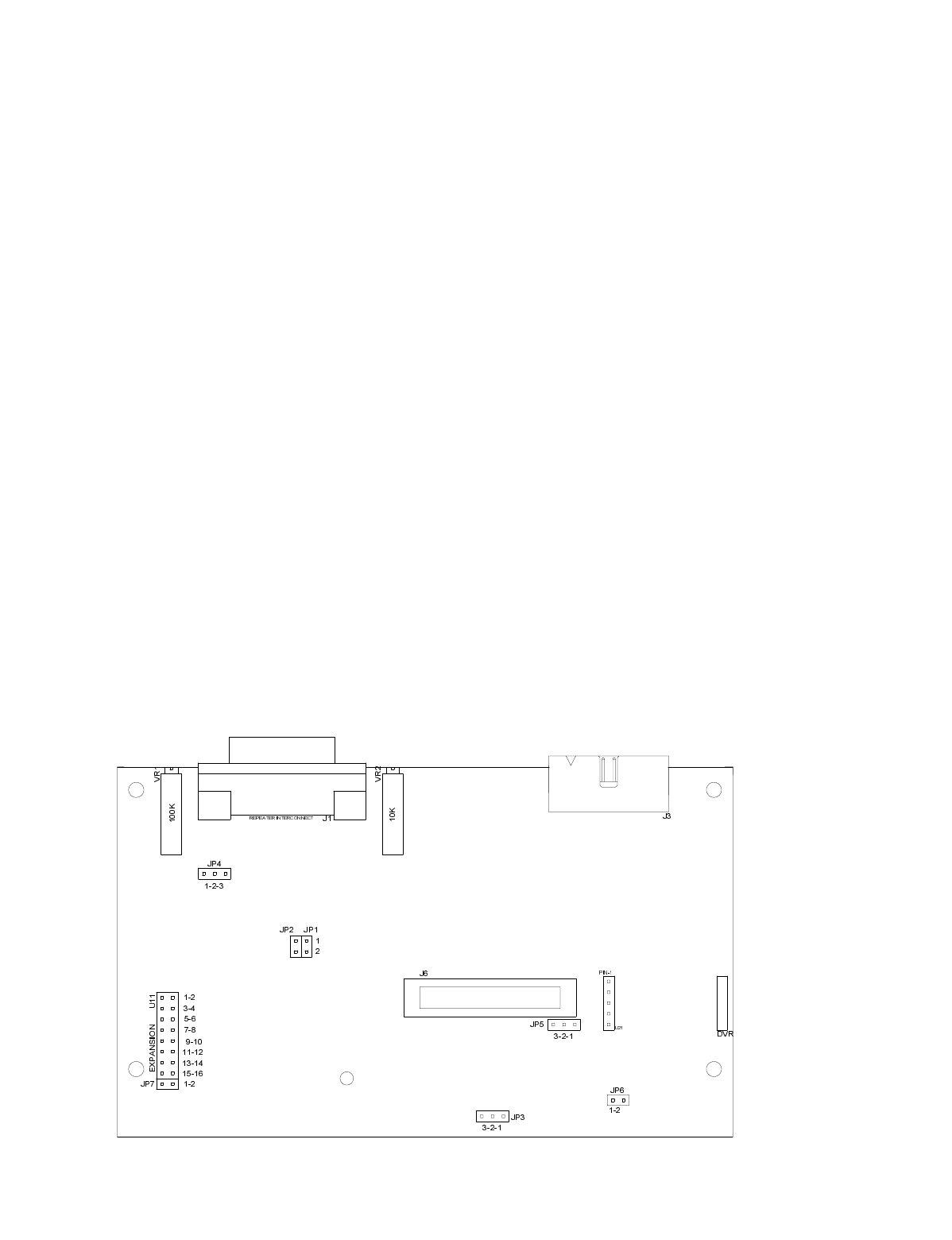
ANALOG CIRCUIT BOARD CONFIGURATION JUMPERS
JP1 - Modulation Select:
This jumper is used in conjunction with JP5 to select when driving a phased or pre-emphasized modulator. Install a
jumper to drive a phase or pre-emphasized modulator. Do not install jumper or leave open if driving a true FM
modulator or modulator without pre-emphasis.
JP5 - Modulation Select:
This jumper is used in conjunction with JP1 to select when driving a phased or pre-emphasized modulator. Install
jumper between pins 1-2 to drive a phase or pre-emphasized modulator. Install a jumper between pins 2-3 driving a
true FM modulator or modulator without pre-emphasis.
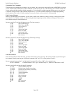
JP2 - Auxiliary Buss Audio Select:
This jumper is used in conjunction with JP3 to select the type of audio to be used on the auxiliary buss. Install a
jumper to select flat audio (audio without pre- emphasis or de-emphasizes). Do not install jumper or leave open to
select pre-emphasis or de-emphasis audio.
JP3 - Auxiliary Buss Audio Select:
This jumper is used in conjunction with JP2 to select the type of audio to be used on the auxiliary buss. Install a
jumper between pins 1-2 to select flat audio (audio without pre- emphasis or de-emphasizes). Install jumper between
pins 2-3 to select pre-emphasis or de-emphasis audio.
JP4 - DCS Modulation Output Select:
This jumper is used to select how the DCS is connected to your transmitter. Install a jumper between pins 1-2 to
output DCS audio on J1 pin 11. Use this configuration when your transmitter has an input designed specifically for
DCS modulation. Install jumper between pins 2-3 to sum DCS audio with the voice audio. This selection can be used
with transmitters with audio inputs that are flat down to 2 Hz.
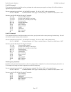
JP6 - Scrambler:
When installing a voice scrambler, use this jumper to break the audio connection to the transmitter for installing a
scrambler. This will allow system and telephone audio to be scrambled. Install a jumper in this location for normal
repeater operation.
JP7 - Band Pass Filter:
This jumper is used when installing a band pass filter for in band tone decoding. Install a jumper in this location for
normal repeater operation.
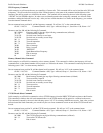
U11 - Expansion Port:
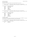
This port is used when installing various options. When this port is not in use, install jumpers between pins 1-2, pins
3-4, pins 5-6 and pins 7-8 only.


