Pacific Research Solutions RI-300e User Manual
Page 10
U.S. Robotics 56K External Modem Set Up
1. Set the dipswitch on the modem. Set switch 3 and 8 down all others up.
2. Connect the modem to your computer using a standard computer-to-modem cable.
3. Run the Hyper Terminal program.
4. Set up Hyper Terminal to communicate to the comm. port to which the external modem is connected, 9600 baud, no parity,
8 data bits, 1 stop bit. The baud rate used must be 9600 and cannot be changed.
5. Power the modem.
6. Type “AT”, the modem should respond with “OK” if you do not get a response, do not proceed. You need to get the
modem to respond before you continue. Check the cable, comm. port and switch settings.
7. Type “AT&F1&W0” (last digit is zero, not oh). This restores the factory defaults and saves these defaults to the EPROM.
The modem will respond with “OK”
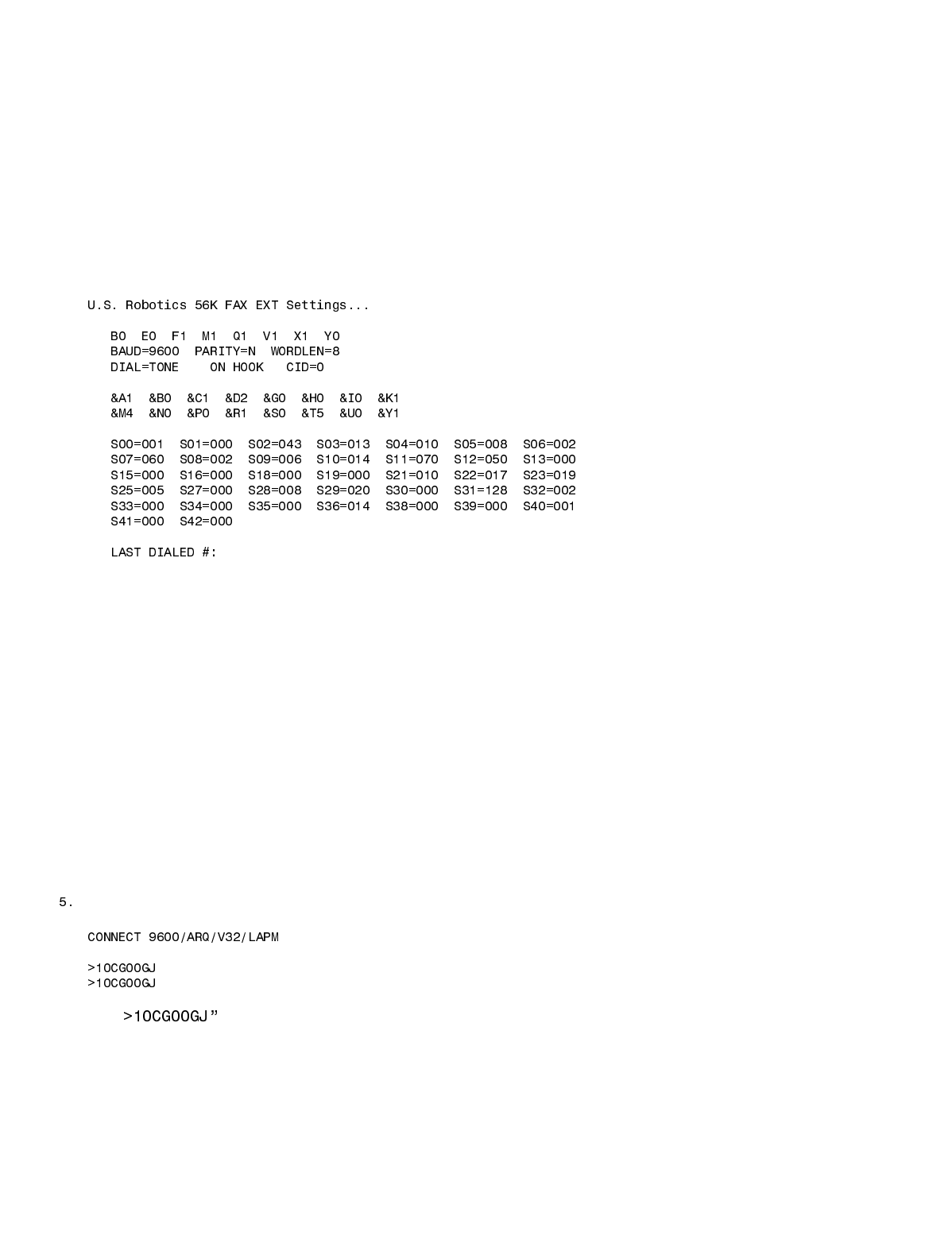
8. Type “ATI4” the modem should respond with the following information. Confirm that everything is set correctly set.
9. If you plan to use the Ring Delay method to connect to your modem, do the following
a. To change the number of rings on which to auto answer, to 4 rings, type “ATS0=4&W0” and the modem should
respond with “OK”. You can replace the “4” value with any value that will work for you application.
b. Turn the power to your external modem off and then on
c. Type “ATI4” to confirm that your new settings are now permanently saved.
10. Turn off the modem and disconnect it from your computer.
11. Change the modem dipswitch settings: (switch 4 down all others up).
12. Attach the modem to the controller using the appropriate cable as discussed early in this section.
13. Apply power to the modem. You are now ready to use the programming software to connect to your controller.
Modem Trouble Shooting
If you are still having problems connecting to your modem, try the following:
1. Restart Hyper Terminal, but set it to communicate to the comm. port that is attached to your internal mode.
2. Set Hyper Terminal to connect at 9600 baud, no parity, 8 data bits, 1 stop bit.
3. Type “AT” and the internal modem should respond with “OK”.
4. Type “ATD[telephone number]”, replace [telephone number] with the telephone number to which the controller is
connected.
After the modem connects, you should see the following message:
6. The “ is a message from the controller and should repeat every 2 seconds.
7. If the modem will not answer, check your dipswitch settings and cables.
8. When the modem is idle (not connected) you should see the following LED status:
AA = ON CD=OFF RD=OFF SD=Flash every 2 seconds TR=ON CS=ON ARQ=OFF
9. When the modem is connected you should see the following LED status:
AA = ON CD=ON RD=OFF SD=Flash every 2 seconds TR=ON CS=ON ARQ=ON
10. If you do not see the controller message, check all cables.
