


Installing the KIRK Repeater 51
KIRK Wireless Server 600v3 Installation and Configuration Guide
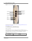
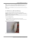
5.1.3 KIRK Repeater - Appearance and Components
The repeater connection panel includes the following:
• Power supply connection (connection for
programming the repeater as well).
Note: The power supply for the repeater is to be ordered separately (Part no. UK version: 84642421,
Part no. EU version: 84642420, Part no. US version: 84642432).
• Antenna connector for repeaters supplied with external antenna connection.
Note: The external antenna incl. antenna cable is to be ordered separately (part no. 02319505).
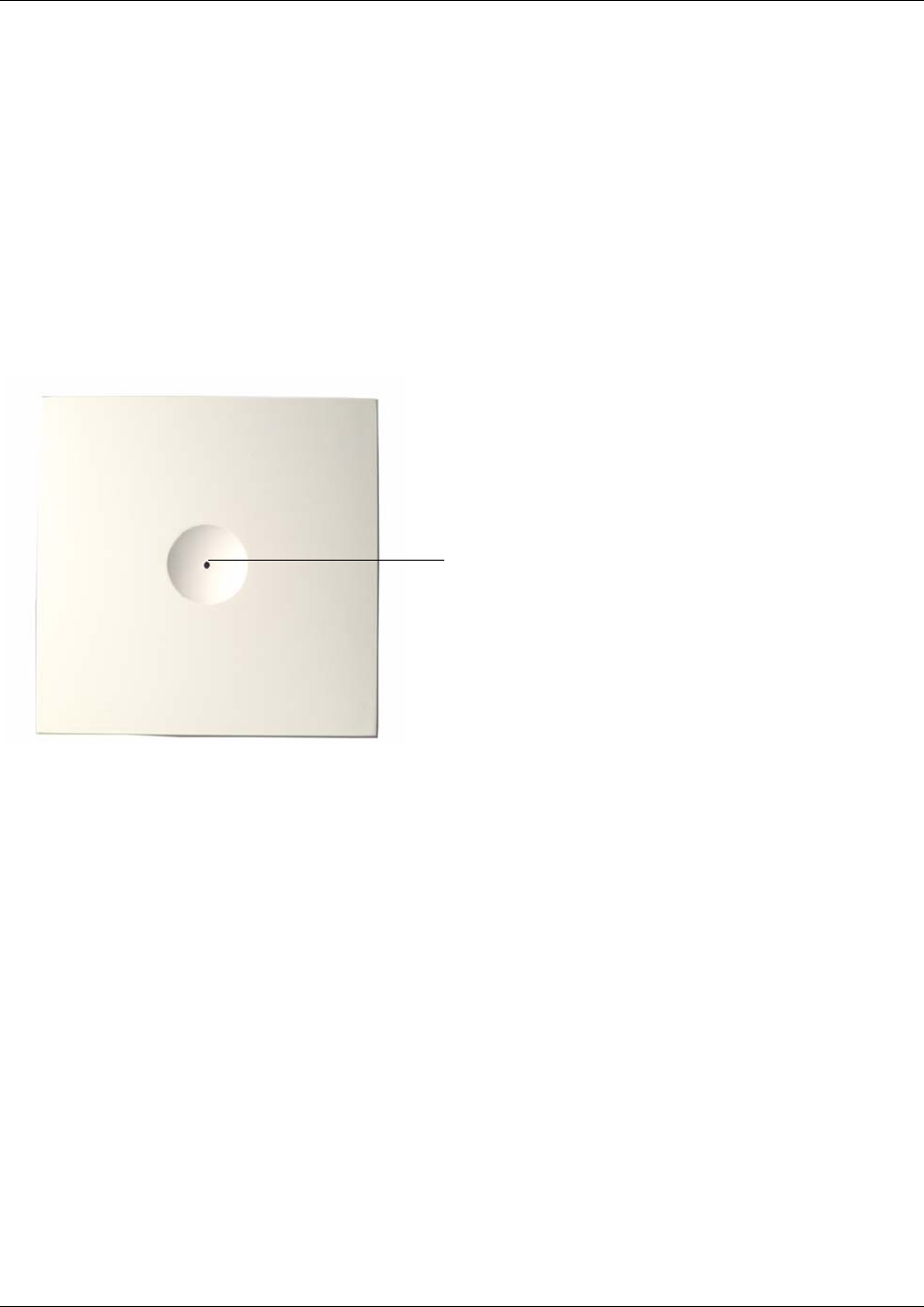
• LED that indicates whether or not the unit is functioning.
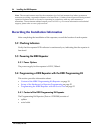
Figure 5-1 Repeater
LED
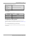
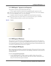
5.1.4 KIRK Repeater LED Indicators
The repeater has one LED indicator describing the repeater operations. The indicator is
off when the repeater is not powered. The LED flashes when the repeater initializes, and
it is on when the repeater is in sync. The LED flashes each time a connected handset is off
or on hook or makes handover from or to a repeater.
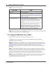
5.1.5 Installing the KIRK Repeater
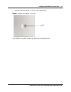
Before beginning the installation, determine the position of the repeater for best coverage.
The coverage depends on the construction of the building, architecture, and the choice of
building materials.
5.1.5.1 Environmental requirements
• Avoid installing repeaters on large concrete or marble columns because these
columns affect radio coverage. If possible, place the base station a minimum of one
meter/3.3 feet from these types of columns.