


DE2-70 User Manual
12
close that port; you cannot use Quartus II to download a configuration file into the FPGA
until you close the USB port.
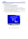
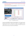
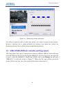
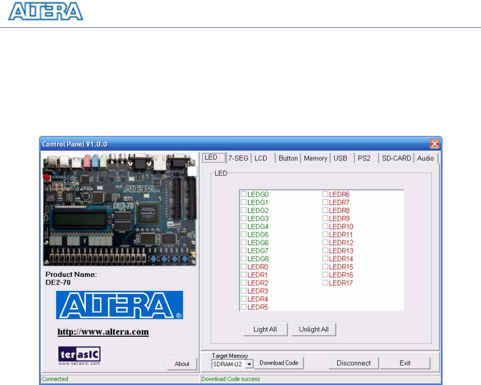
7. The Control Panel is now ready for use; experiment by setting the value of some LEDs
display and observing the result on the DE2-70 board.
Figure 3.1. The DE2-70 Control Panel.
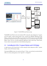
The concept of the DE2-70 Control Panel is illustrated in Figure 3.2. The “Control Codes” that
performs the control functions is implemented in the FPGA board. It communicates with the
Control Panel window, which is active on the host computer, via the USB Blaster link. The
graphical interface is used to issue commands to the control codes. It handles all requests and
performs data transfers between the computer and the DE2-70 board.