


DE2-70 User Manual
40
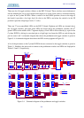
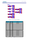
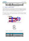
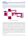
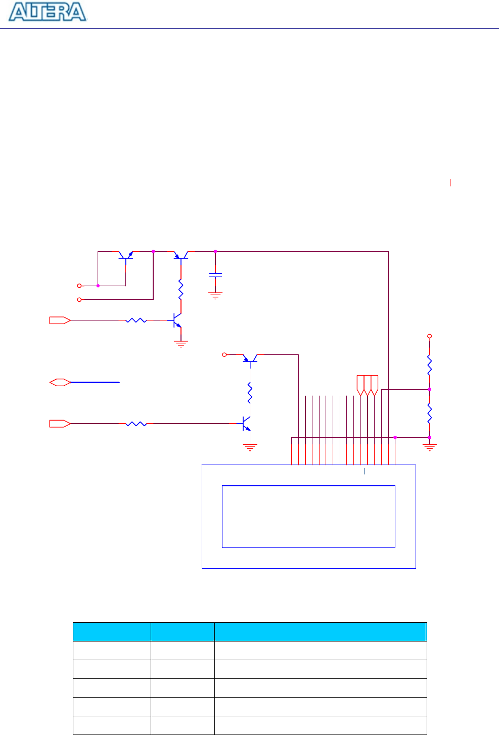
5.5 Using the LCD Module
The LCD module has built-in fonts and can be used to display text by sending appropriate
commands to the display controller, which is called HD44780. Detailed information for using the
display is available in its datasheet, which can be found on the manufacturer's web site, and from
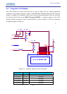
the Datasheet/LCD folder on the DE2-70 System CD-ROM. A schematic diagram of the LCD
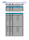
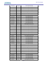
module showing connections to the Cyclone II FPGA is given in Figure 5.9. The associated pin
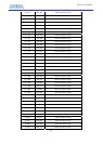
assignments appear in Table 5.6.
LCD_D2
LCD_VCC
LCD_D0
LCD_D6
LCD_D7
LCD_D1
LCD_D4
LCD_BL
LCD_D3
L
CD_D5
LCD_CONT
L
CD_D[0..7]
LCD_BLON
LCD_ON
LCD_EN
LCD_RS
LCD_R
W
VCC43
VCC43
VCC43
VCC5
R38
1K
R38
1K
2 X 16 DIGIT LCD
DIS1
LCD-2x16
2 X 16 DIGIT LCD
DIS1
LCD-2x16
GND
1
VCC
2
CONT
3
RS
4
RW
5
EN
6
D0
7
D1
8
D2
9
D3
10
D4
11
D5
12
D6
13
D7
14
BL
15
GND
16
Q5
8050
Q5
8050
R39
47
R39
47
R36
680
R36
680
R37
680
R37
680
Q3
8050
Q3
8050
Q4 8550Q4 8550
C6
1u
C6
1u
Q2 8550Q2 8550
Q1 8050Q1 8050
R35
680
R35
680
R34
680
R34
680
Figure 5.9. Schematic diagram of the LCD module.
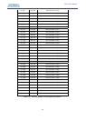
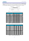
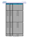
Signal Name FPGA Pin No. Description
LCD_DATA[0] PIN_E1 LCD Data[0]
LCD_DATA[1] PIN_E3 LCD Data[1]
LCD_DATA[2] PIN_D2 LCD Data[2]
LCD_DATA[3] PIN_D3 LCD Data[3]
LCD_DATA[4] PIN_C1 LCD Data[4]