


DE2-70 User Manual
70
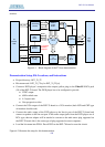
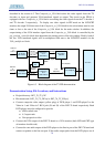
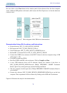
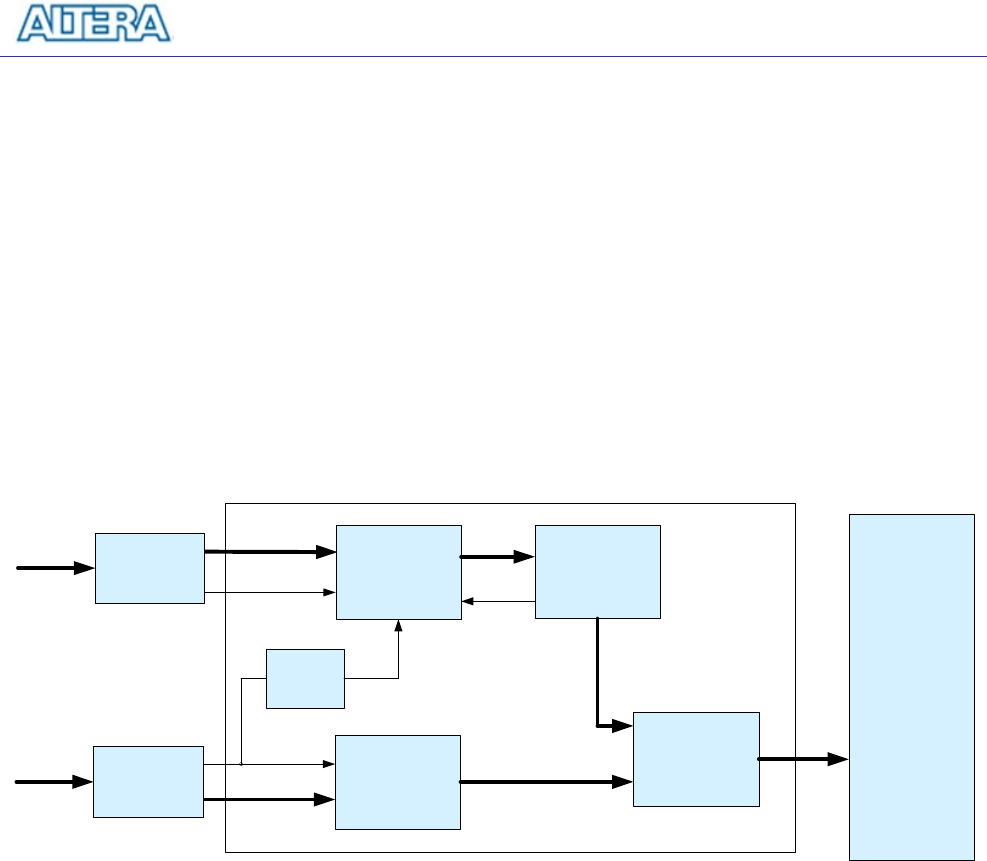
described in the section 6.2. The Composite_to_VGA block takes the video signals from the TV
decoders as input and generate VGA-interfaced signals as output. The circuit in the FPGA is
equipped with two Composite_to_VGA blocks converting the video signals from the TV decoder 1
and TV decoder 2 respectively. To display two video signals in PIP mode on the LCD/CRT
monitor, the output VGA data rate of the Composite_to_VGA block for the sub window must be two
times as fast as the rate of the Composite_to_VGA block for the main window. In addition, the
output timing of the VGA interface signal from the Composite_to_VGA block is controlled by the
pip_position_controller block that determines the stating poison of the sub window. Finally, both of
the two VGA interfaced signals will be multiplexed and sent to the LCD/CRT monitor via the
VGA_multiplexer block.
Composite_to_
VGA
(Sub window)
TD_clock_
PLL
Composite_to_
VGA
(Main window)
TD_clock
54Mhz
TD data
TD_clock
TD data
(27Mhz)
PiP_position_
controller
VGA data
VGA multiplexer
VGA
data(Main)
VGA data(Sub)
Control
signal
VGA DAC
VGA data
TV decoder
(Sub window)
TV decoder
(Main window)
Video in 1
or
Video in 2
Video in 2
or
Video in 1
Figure 6.3. Block diagram of the TV PIP demonstration.
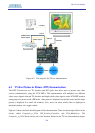
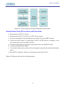
Demonstration Setup, File Locations, and Instructions
• Project directory: DE2_70_TV_PIP
• Bit stream used: DE2_70_TV_PIP.sof or DE2_70_TV_PIP.pof
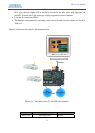
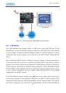
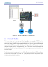
• Connect composite video output (yellow plug) of DVD player 1 and DVD player2 to the
Video-in 1 and Video-in 2 RCA jack (J8 and J9) of the DE2-70 board respectively. Both
DVD players must be configured to provide
o 60 Hz refresh rate
o 4:3 aspect ratio
o Non-progressive video
• Connect the VGA output of the DE2-70 board to a VGA monitor (both LCD and CRT type
of monitors should work)
• Connect the one audio output of the DVD player to the line-in port of the DE2-70 board and
connect a speaker to the line-out port. If the audio output jacks from the DVD player are of