


DE2-70 User Manual
33
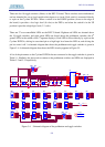
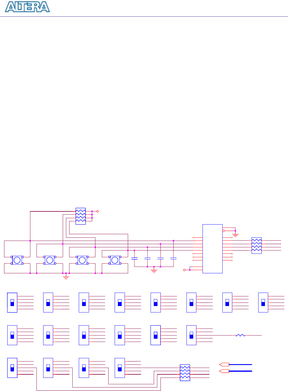
There are also 18 toggle switches (sliders) on the DE2-70 board. These switches are not debounced,
and are intended for use as level-sensitive data inputs to a circuit. Each switch is connected directly
to a pin on the Cyclone II FPGA. When a switch is in the DOWN position (closest to the edge of
the board) it provides a low logic level (0 volts) to the FPGA, and when the switch is in the UP
position it provides a high logic level (3.3 volts).
There are 27 user-controllable LEDs on the DE2-70 board. Eighteen red LEDs are situated above
the 18 toggle switches, and eight green LEDs are found above the pushbutton switches (the 9
th
green LED is in the middle of the 7-segment displays). Each LED is driven directly by a pin on the
Cyclone II FPGA; driving its associated pin to a high logic level turns the LED on, and driving the
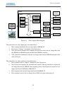
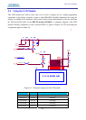
pin low turns it off. A schematic diagram that shows the pushbutton and toggle switches is given in
Figure 5.4. A schematic diagram that shows the LED circuitry appears in Figure 5.5.
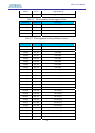
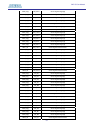
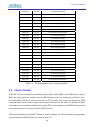
A list of the pin names on the Cyclone II FPGA that are connected to the toggle switches is given in
Table 5.1. Similarly, the pins used to connect to the pushbutton switches and LEDs are displayed in
Tables 5.2 and 5.3, respectively.
GND
GND
VCC33
GND
GND
GND
GND
VCC33
GND
GND
VCC33
GND
GND
GND
GND
VCC33
SW3
SW2
SW1
SW0
VCC33
GND
GND
GND
GND
VCC33
GND
GND
VCC33
GND
GND
GND
GND
VCC33
GND
GND
SW7
SW6
SW5
SW4
KEYIN0
SW12
GND
VCC33
GN
D
GND
GND
GND
VCC33
VCC33
GND
GND
GND
GND
VCC33
GND
GND
VCC33
GND
GND
GND
GND
VCC33
GND
GND
SW11
SW10
SW9
SW8
GND
GND
VCC33
VCC33
GND
GND
GND
GN
D
GND
GND
GND
VCC33
GND
GND
GND
GND
VCC33
SW14
SW17
SW15
SW16
KEY0
KEY2
KEY3
KEY1
SW13
KEYIN1
KEYIN2
KEYIN3
SW[0..17]
KEY[0..3]
VCC33
VCC33
SW13
SLIDE SW
SW13
SLIDE SW
1
2
3
4
5
BUTTON2
T
ACT SW
BUTTON2
T
ACT SW
4
3
2
1
C13
1u
C13
1u
U8
74HC245
U8
74HC245
A1
2
A2
3
A3
4
A4
5
A5
6
A6
7
A7
8
A8
9
OE
19
DIR
1
B1
18
B2
17
B3
16
B4
15
B5
14
B6
13
B7
12
B8
11
VCC
20
GND
10
SW6
SLIDE SW
SW6
SLIDE SW
1
2
3
4
5
RN35
120
RN35
120
1
2
3
4
5
6
7
8
SW16
SLIDE SW
SW16
SLIDE SW
1
2
3
4
5
BUTTON0
TACT SW
BUTTON0
TACT SW
4
3
2
1
SW7
SLIDE SW
SW7
SLIDE SW
1
2
3
4
5
RN33
100K
RN33
100K
1
2
3
4
5
6
7
8
SW17
SLIDE SW
SW17
SLIDE SW
1
2
3
4
5
C16
1u
C16
1u
SW8
SLIDE SW
SW8
SLIDE SW
1
2
3
4
5
R50
120
R50
120
SW14
SLIDE SW
SW14
SLIDE SW
1
2
3
4
5
BUTTON3
TACT SW
BUTTON3
TACT SW
4
3
2
1
SW1
SLIDE SW
SW1
SLIDE SW
1
2
3
4
5
C14
1u
C14
1u
SW9
SLIDE SW
SW9
SLIDE SW
1
2
3
4
5
SW15
SLIDE SW
SW15
SLIDE SW
1
2
3
4
5
SW0
SLIDE SW
SW0
SLIDE SW
1
2
3
4
5
SW2
SLIDE SW
SW2
SLIDE SW
1
2
3
4
5
SW10
SLIDE SW
SW10
SLIDE SW
1
2
3
4
5
BUTTON1
TACT SW
BUTTON1
TACT SW
4
3
2
1
SW3
SLIDE SW
SW3
SLIDE SW
1
2
3
4
5
RN34
120
RN34
120
1
2
3
4
5
6
7
8
SW11
SLIDE SW
SW11
SLIDE SW
1
2
3
4
5
SW4
SLIDE SW
SW4
SLIDE SW
1
2
3
4
5
C15
1u
C15
1u
SW12
SLIDE SW
SW12
SLIDE SW
1
2
3
4
5
SW
5
SLIDE SW
SW
5
SLIDE SW
1
2
3
4
5
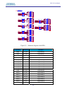
Figure 5.4. Schematic diagram of the pushbutton and toggle switches.