


DE2-70 User Manual
36
LEDG[7] PIN_ AA24 LED Green[7]
LEDG[8] PIN_ AC14 LED Green[8]
Table 5.3. Pin assignments for the LEDs.
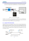
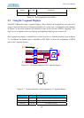
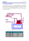
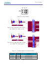
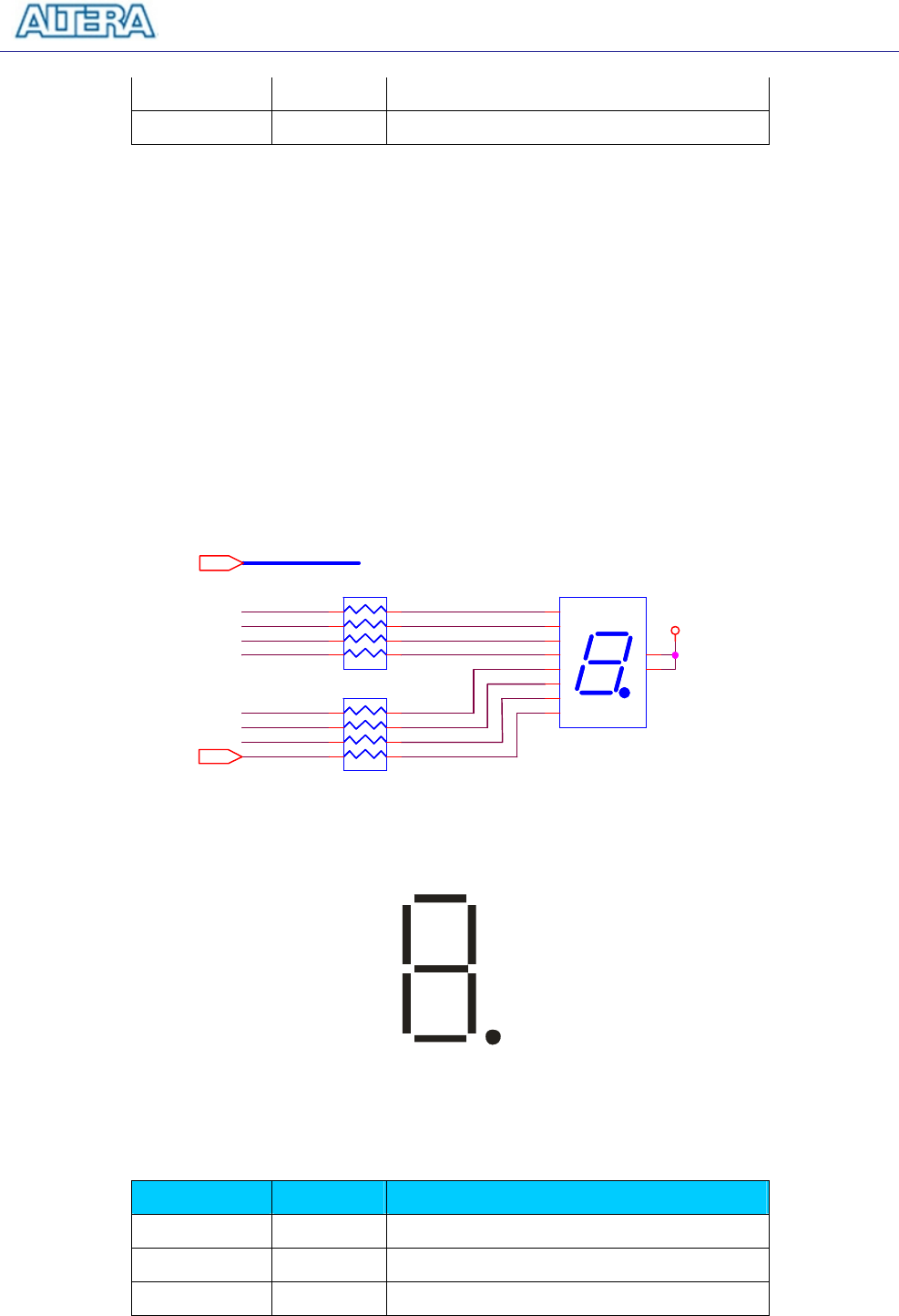
5.3 Using the 7-segment Displays
The DE2-70 Board has eight 7-segment displays. These displays are arranged into two pairs and a
group of four, with the intent of displaying numbers of various sizes. As indicated in the schematic
in Figure 5.6, the seven segments are connected to pins on the Cyclone II FPGA. Applying a low
logic level to a segment causes it to light up, and applying a high logic level turns it off.
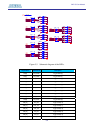
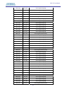
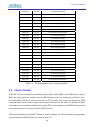
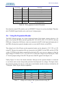
Each segment in a display is identified by an index from 0 to 6, with the positions given in Figure
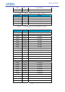
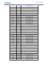
5.7. In addition, the decimal point is identified as DP. Table 5.4 shows the assignments of FPGA
pins to the 7-segment displays.
F0
HEX0_D4
HEX0_D3
HEX0_D2
HEX0_D6
HEX0_D1
HEX0_D5
HEX0_D0
E0
B0
C0
A0
D0
G0
DP0
HEX0_D[0..6]
HEX0_DP
VCC3
3
e
d
dp
c
g
b
f
a
CA1
CA2
HEX0
7Segment Display
e
d
dp
c
g
b
f
a
CA1
CA2
HEX0
7Segment Display
1
2
3
4
5
6
10
9
8
7
RN17
1K
RN17
1K
1
2
3
4
5
6
7
8
RN18
1K
RN18
1K
1
2
3
4
5
6
7
8
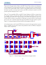
Figure 5.6. Schematic diagram of the 7-segment displays.
0
3
1
24
5
6
DP
Figure 5.7. Position and index of each segment in a 7-segment display.
Signal Name FPGA Pin No. Description
HEX0_D[0] PIN_AE8 Seven Segment Digit 0[0]
HEX0_D[1] PIN_AF9 Seven Segment Digit 0[1]
HEX0_D[2] PIN_AH9 Seven Segment Digit 0[2]