


DE2-70 User Manual
49
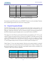
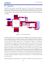
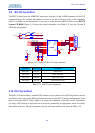
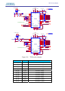
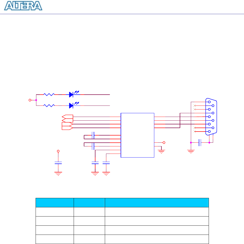
5.9 RS-232 Serial Port
The DE2-70 board uses the ADM3202 transceiver chip and a 9-pin D-SUB connector for RS-232
communications. For detailed information on how to use the transceiver refer to the datasheet,
which is available on the manufacturer’s web site, or in the Datasheet/RS232 folder on the DE2-70
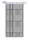
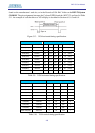
System CD-ROM. Figure 5.15 shows the related schematics, and Table 5.13 lists the Cyclone II
FPGA pin assignments.
UART_RXD
UART_TXD
TXD
RXD
CTS
RTS
UART_CTS
UAR
T_TXD
UART_RXD
UART_RTS
VCC33
VCC33
VCC33
J2
RS232
J2
RS232
5
9
4
8
3
7
2
6
1
11
10
C10
1u
C10
1u
RXD
LEDR
RXD
LEDR
BC32 0.1uBC32 0.1u
C9
1u
C9
1u
U7
ADM3202
U7
ADM3202
R1IN
13
R2IN
8
T1IN
11
T2IN
10
C+
1
C1-
3
C2+
4
C2-
5
V+
2
V-
6
R1OUT
12
R2OUT
9
T1OUT
14
T2OUT
7
VCC
16
GND
15
R44
330
R44
330
R45
330
R45
330
BC33
0.1u
BC33
0.1u
C11
1u
C11
1u
TXD
LEDG
TXD
LEDG
C12
1u
C12
1u
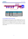
Figure 5.15. MAX232 (RS-232) chip schematic.
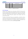
Signal Name FPGA Pin No. Description
UART_RXD PIN_D21 UART Receiver
UART_TXD PIN_E21 UART Transmitter
UART_CTS PIN_G22 UART Clear to Send
UART_RTS PIN_F23 UART Request to Send
Table 5.13. RS-232 pin assignments.
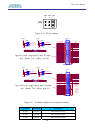
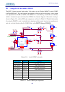
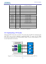
5.10 PS/2 Serial Port
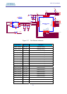
The DE2-70 board includes a standard PS/2 interface and a connector for a PS/2 keyboard or mouse.
In addition, users can use the PS/2 keyboard and mouse on the DE2-70 board simultaneously by an
plug an extension PS/2 Y-Cable. Figure 5.16 shows the schematic of the PS/2 circuit. Instructions
for using a PS/2 mouse or keyboard can be found by performing an appropriate search on various
educational web sites. The pin assignments for the associated interface are shown in Table 5.14.