


DE2-70 User Manual
88
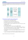
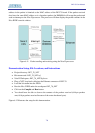
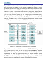
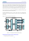
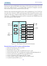
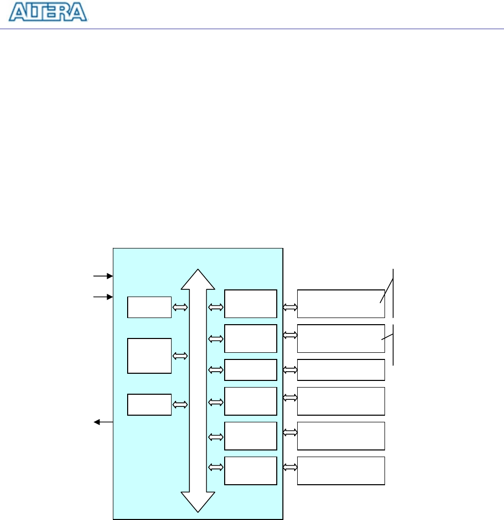
hardware part is built by SOPC Builder under Quartus II. The hardware part includes all the other
blocks. The “AUDIO Controller” is a user-defined SOPC component. It is designed to send audio
data to the audio chip or receive audio data from the audio chip.
The audio chip is programmed through I2C protocol which is implemented in C code. The I2C pin
from audio chip is connected to SOPC System Interconnect Fabric through PIO controllers. In this
example, the audio chip is configured in Master Mode. The audio interface is configured as I2S and
16-bit mode. A 18.432MHz clock generated by the PLL is connected to the XTI/MCLK pin of the
audio chip through the AUDIO Controller.
Figure 6.19. Block diagram of the audio recorder and player.
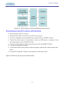
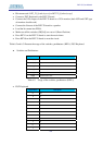
Demonstration Setup, File Locations, and Instructions
• Hardware Project directory: DE2_70_AUDIO
• Bit stream used: DE2P_TOP.sof
• Software Project directory: DE2_70_AUDIO\software\project_audio
• Software Execution File: DE2_70_AUDIO\software\project_auido\audio\debug\audio.elf
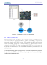
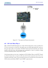
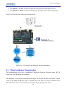
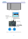
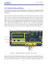
• Connect an Audio Source to the LINE-IN port of the DE2-70 board.
• Connect a Microphone to MIC-IN port on the DE2-70 board.
• Connect a speaker or headset to LINE-OUT port on the DE2-70 board.
• Load the bit stream into FPGA. (note *1)
SOPC
S
y
stem Interconnect Fabric
NIOS II
PIO
JTAG
UART
SEG7
Co
n
t
r
o
ll
er
PLL
LCD
Co
n
t
r
o
ll
er
SDRAM
Co
n
t
r
o
ll
er
SRAM
Co
n
t
r
o
ll
er
SDRAM
SRAM
LCD
SEG7
AUDIO
AUDIO
Co
n
t
r
o
ll
er
LED/KEY/SW/I2C
50M Hz
RESE
_
N
Clock
to
SDRAM
SRAM
Store
Audio
Data
Nios II
Program