


DE2-70 User Manual
32
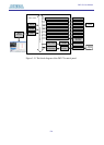
position and then reset the board by turning the power switch off and back on; this action
causes the new configuration data in the EPCS16 device to be loaded into the FPGA chip.
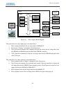
USB Blaster Circuit
EPCS16
Serial
Configuration
Device
JTAG Config Port
USB
Auto
Power-on Config
MAX
3128
Quartus II
Programmer
AS Mode
PROG RUN/
AS Mode
Config
"PROG"
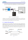
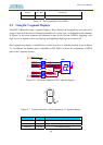
Figure 5.2. The AS configuration scheme.
In addition to its use for JTAG and AS programming, the USB Blaster port on the DE2-70 board
can also be used to control some of the board's features remotely from a host computer. Details that
describe this method of using the USB Blaster port are given in Chapter 3.
5.2 Using the LEDs and Switches
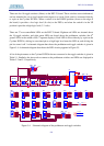
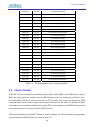
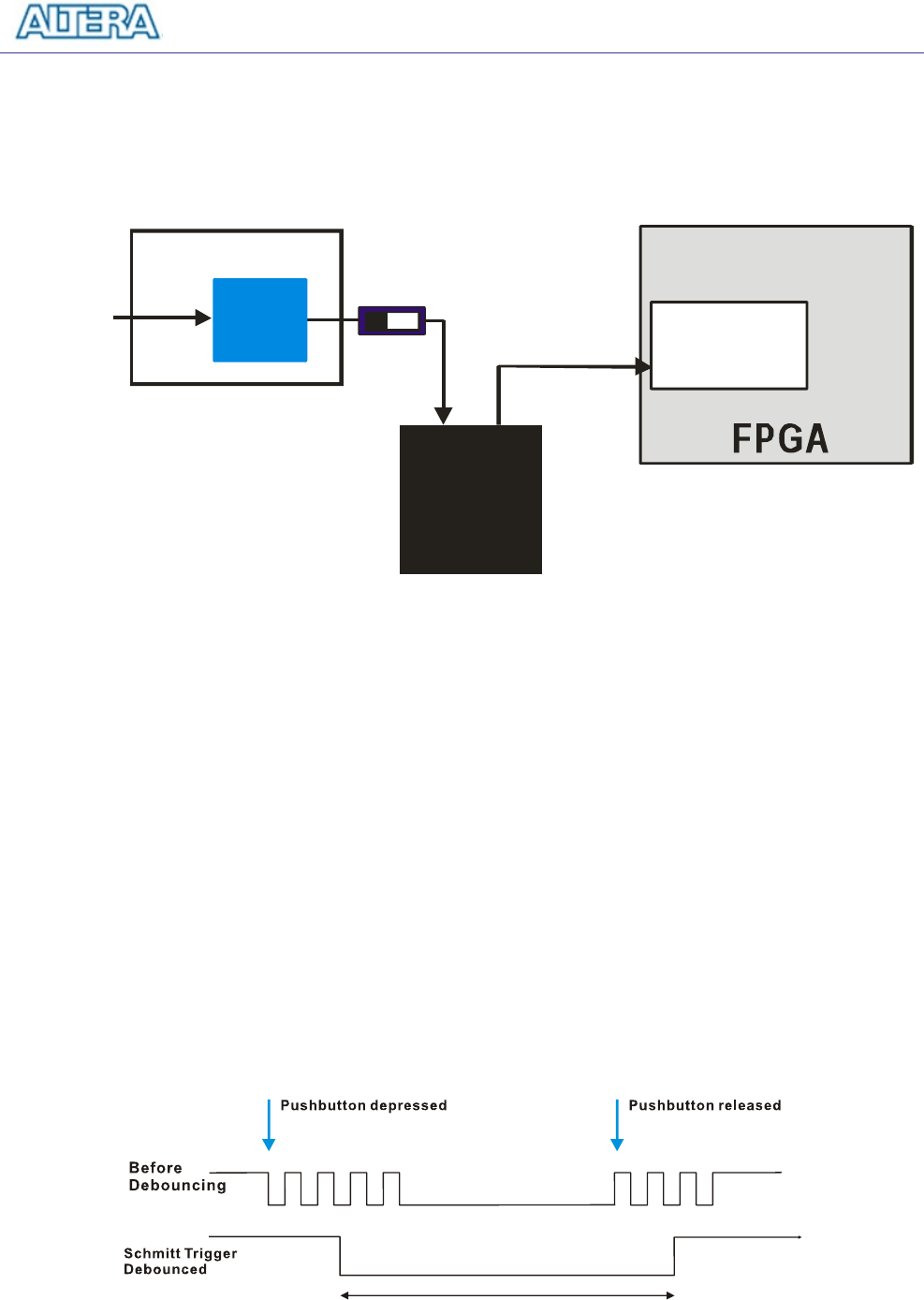
The DE2-70 board provides four pushbutton switches. Each of these switches is debounced using a
Schmitt Trigger circuit, as indicated in Figure 5.3. The four outputs called KEY0, KEY1, KEY2, and
KEY3 of the Schmitt Trigger devices are connected directly to the Cyclone II FPGA. Each switch
provides a high logic level (3.3 volts) when it is not pressed, and provides a low logic level (0 volts)
when depressed. Since the pushbutton switches are debounced, they are appropriate for use as clock
or reset inputs in a circuit.
Figure 5.3. Switch debouncing.