


DE2-70 User Manual
29
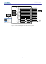
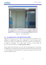
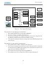
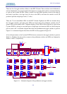
FPGA
SOPC
NIOS II
TIMER
JTAG
System Interconnect Fabric
SDRAM
-U1
SDRAM
Controller
Multi
-Port
SSRAM
Controller
JTAG
Blaster
Hardware
VGA
Controller
SSRAM
VIDEO
-In
Controller
Avalon
MM Slave
VGA
VIDEO IN
NIOS II
Program
SDRAM
-U2
SDRAM
Controll
er
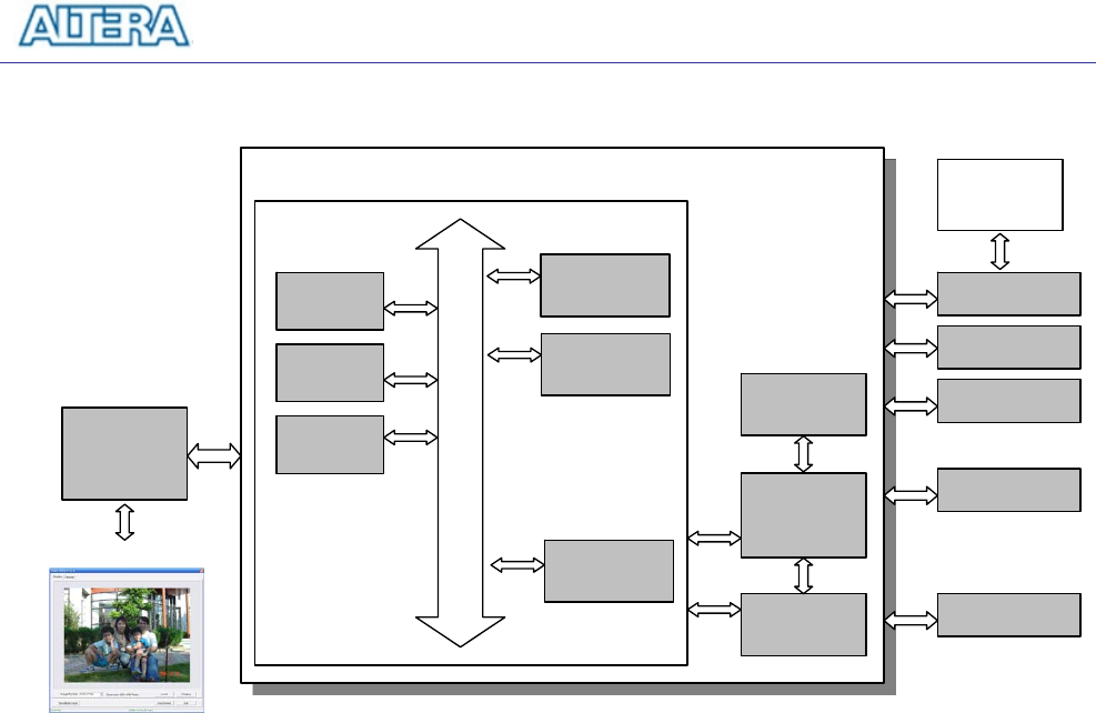
Figure 4.4. Video Capture Block Diagram.
The control flow for video displaying is described below:
1. Host computer downloads the raw image data to SDRAM-U2.
2. Host issues a “display” command to Nios II processor.
3. Nios II processor interprets the command received and moves the raw image data from
the SDRAM to SSRAM through the Multi-Port SSRAM controller.
4. VGA Controller continuously reads the raw image data from the SSRAM and sends them
to the VGA port.
The control flow for video capturing is described below:
1. Host computer issues a “capture” command to Nios II processor.
2. Nios II processor interprets the command and controls Video-In controller to capture the
raw image data into the SSRAM. After capturing is done, Nios II processor copies the raw
image data from the SSRAM to SDRAM-U2.
3. Host computer reads the raw image data from the SDRAM-U2
4. Host computer converts the raw image data to RGB color space and displays it.