


DE2-70 User Manual
50
KBCLK
KBDAT
MSDAT
MSCLK
PS2_KBDAT
PS2_KBCLK
PS2_MSCLK
PS2_MSDAT
VCC5
V
CC5
VCC5
VCC33
VCC33
VCC5
VCC5
VCC33
VCC33
R172
2K
R172
2K
BC35
0.1u
BC35
0.1u
R174
120
R174
120
R175
120
R175
120
D9
BAT54S
D9
BAT54S
1
2
3
D96
BAT54S
D96
BAT54S
1
2
3
D10
BAT54S
D10
BAT54S
1
2
3
BC34
0.1u
BC34
0.1u
D95
BAT54S
D95
BAT54S
1
2
3
R46
2K
R46
2K
R47
2K
R47
2K
R48
120
R48
120
R49
120
R49
120
3
5
T
OP
8
6
2
1
J3
PS2
3
5
T
OP
8
6
2
1
J3
PS2
3
5
6
9
10
11
2
1
8
R173
2K
R173
2K
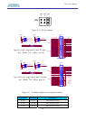
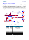
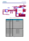
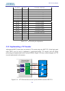
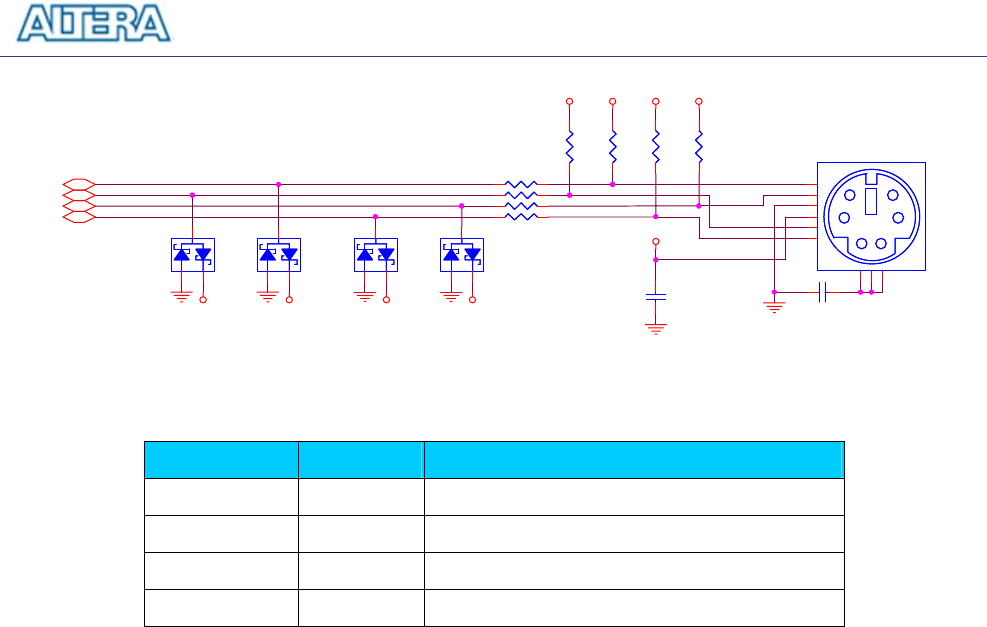
Figure 5.16. PS/2 schematic.
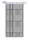
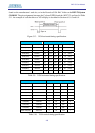
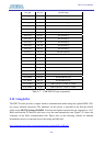
Signal Name FPGA Pin No. Description
PS2_KBCLK PIN_F24 PS/2 Clock
PS2_KBDAT PIN_E24 PS/2 Data
PS2_MSCLK PIN_D26 PS/2 Clock (reserved for second PS/2 device)
PS2_MSDAT PIN_D25 PS/2 Data(reserved for second PS/2 device)
Table 5.14. PS/2 pin assignments.
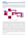
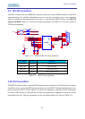
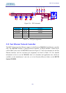
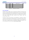
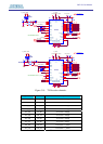
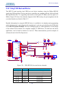
5.11 Fast Ethernet Network Controller
The DE2-70 board provides Ethernet support via the Davicom DM9000A Fast Ethernet controller
chip. The DM9000A includes a general processor interface, 16 Kbytes SRAM, a media access
control (MAC) unit, and a 10/100M PHY transceiver. Figure 5.17 shows the schematic for the Fast
Ethernet interface, and the associated pin assignments are listed in Table 5.15. For detailed
information on how to use the DM9000A refer to its datasheet and application note, which are
available on the manufacturer’s web site, or in the Datasheet/Ethernet folder on the DE2-70
System CD-ROM.