


DE2-70 User Manual
69
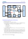
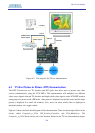
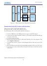
DE-interlace
ITU-R 656
YUV 4:2:2
Decoder
VGA(LCD/CRT)Monitor
Line Out
VGA Out
DVD Player
Video In
Line In
Audio Output
CVBS S-Video
YPbPr Output
Speaker
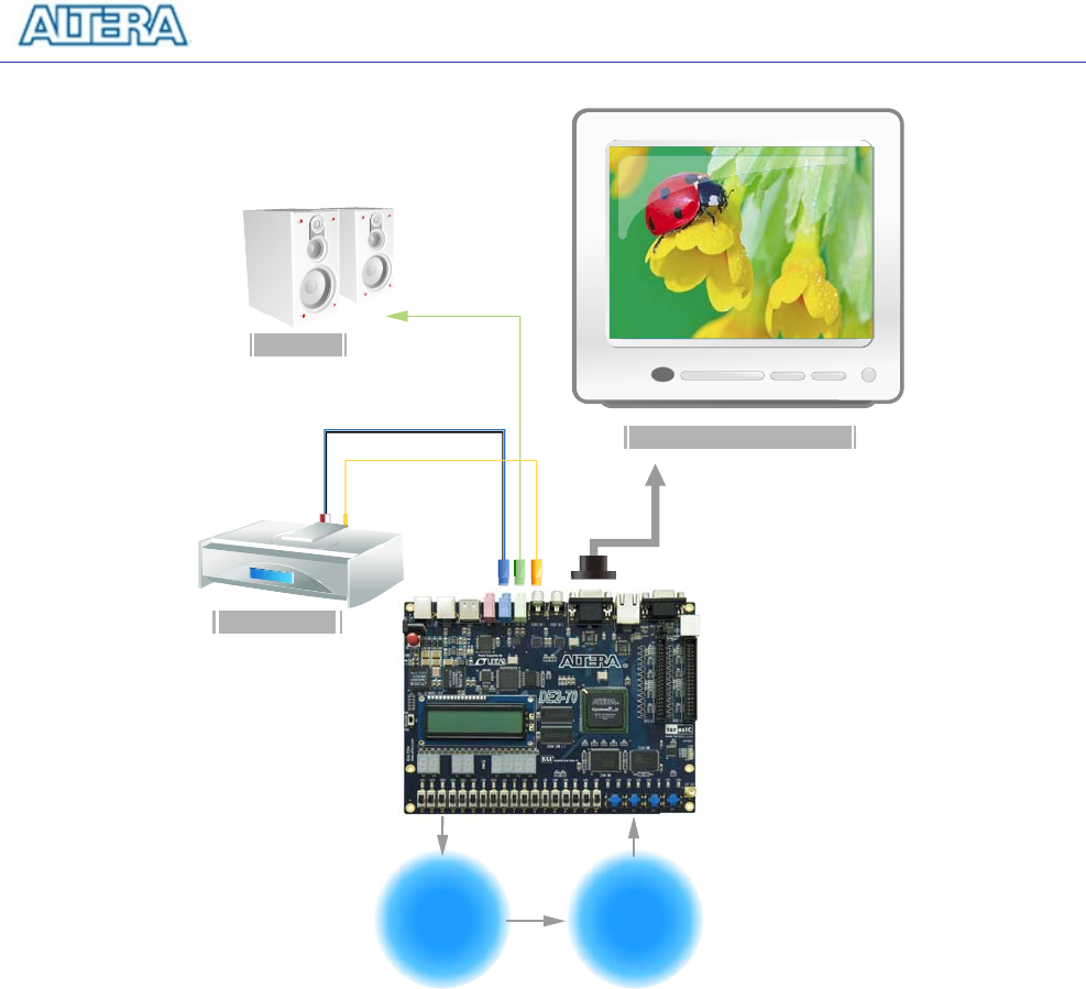
Figure 6.2. The setup for the TV box demonstration.
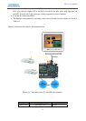
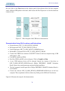
6.3 TV Box Picture in Picture (PIP) Demonstration
The DE2-70 board has two TV decoders and RCA jacks that allow users to process two video
sources simultaneously using the 2C70 FPGA. This demonstration will multiplex two different
video source signals from the TV decoders and display both video signals on the LCD/CRT monitor
using picture in picture mode (PIP mode : One picture is displayed on the full screen and the other
picture is displayed in a small sub window). Also, users can select which video is displayed in
main/sub window via a toggle switch.
Figure 6.3 shows the basic block diagram of this demonstration. There are three major blocks in the
circuit, called Composite_to_VGA, PIP_Position_Controller, and VGA_Multiplexer. The
Composite_to_VGA block consists all of the function blocks in the TV box demonstration project