


DE2-70 User Manual
56
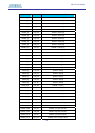
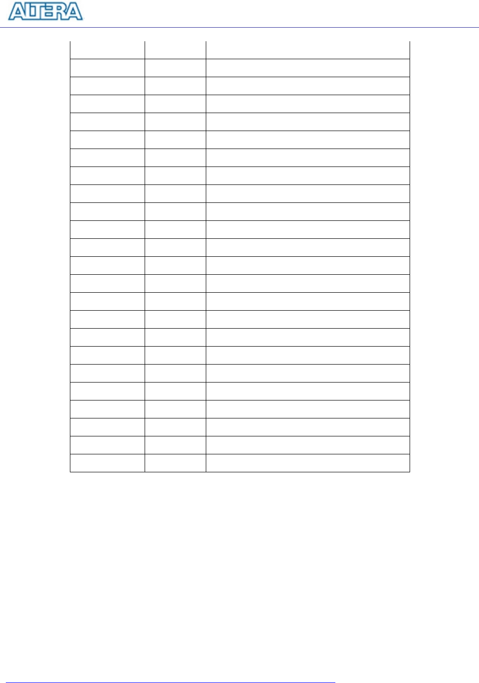
OTG_D[4] PIN_J12 ISP1362 Data[4]
OTG_D[5] PIN_H12 ISP1362 Data[5]
OTG_D[6] PIN_H13 ISP1362 Data[6]
OTG_D[7] PIN_G13 ISP1362 Data[7]
OTG_D[8] PIN_D4 ISP1362 Data[8]
OTG_D[9] PIN_D5 ISP1362 Data[9]
OTG_D[10] PIN_D6 ISP1362 Data[10]
OTG_D[11] PIN_E7 ISP1362 Data[11]
OTG_D[12] PIN_D7 ISP1362 Data[12]
OTG_D[13] PIN_E8 ISP1362 Data[13]
OTG_D[14] PIN_D9 ISP1362 Data[14]
OTG_D[15] PIN_G10 ISP1362 Data[15]
OTG_CS_N PIN_E10 ISP1362 Chip Select
OTG_OE_N PIN_D10 ISP1362 Read
OTG_WE_N PIN_E11 ISP1362 Write
OTG_RESET_N PIN_H14 ISP1362 Reset
OTG_INT0 PIN_F13 ISP1362 Interrupt 0
OTG_INT1 PIN_J13 ISP1362 Interrupt 1
OTG_DACK0_N PIN_D12 ISP1362 DMA Acknowledge 0
OTG_DACK1_N PIN_E12 ISP1362 DMA Acknowledge 1
OTG_DREQ0 PIN_G12 ISP1362 DMA Request 0
OTG_DREQ1 PIN_F12 ISP1362 DMA Request 1
OTG_FSPEED PIN_F7 USB Full Speed, 0 = Enable, Z = Disable
OTG_LSPEED PIN_F8 USB Low Speed, 0 = Enable, Z = Disable
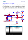
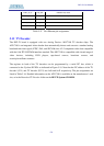
Table 5.17. USB (ISP1362) pin assignments.
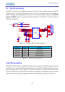
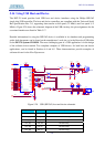
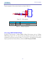
5.15 Using IrDA
The DE2-70 board provides a simple wireless communication media using the Agilent HSDL-3201
low power infrared transceiver. The datasheet for this device is provided in the Datasheet\IrDA
folder on the DE2-70 System CD-ROM. Note that the highest transmission rate supported is 115.2
Kbit/s and both the TX and RX sides have to use the same transmission rate. Figure 5.21 shows the
schematic of the IrDA communication link. Please refer to the following website for detailed
information on how to send and receive data using the IrDA link:
http://techtrain.microchip.com/webseminars/documents/IrDA_BW.pdf