


DE2-70 User Manual
5
(AS) programming modes are supported
• 2-Mbyte SSRAM
• Two 32-Mbyte SDRAM
• 8-Mbyte Flash memory
• SD Card socket
• 4 pushbutton switches
• 18 toggle switches
• 18 red user LEDs
• 9 green user LEDs
• 50-MHz oscillator and 28.63-MHz oscillator for clock sources
• 24-bit CD-quality audio CODEC with line-in, line-out, and microphone-in jacks
• VGA DAC (10-bit high-speed triple DACs) with VGA-out connector
• 2 TV Decoder (NTSC/PAL/SECAM) and TV-in connector
• 10/100 Ethernet Controller with a connector
• USB Host/Slave Controller with USB type A and type B connectors
• RS-232 transceiver and 9-pin connector
• PS/2 mouse/keyboard connector
• IrDA transceiver
• 1 SMA connector
• Two 40-pin Expansion Headers with diode protection
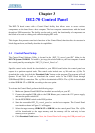
In addition to these hardware features, the DE2-70 board has software support for standard I/O
interfaces and a control panel facility for accessing various components. Also, software is provided
for a number of demonstrations that illustrate the advanced capabilities of the DE2-70 board.
In order to use the DE2-70 board, the user has to be familiar with the Quartus II software. The
necessary knowledge can be acquired by reading the tutorials Getting Started with Altera’s DE2-70
Board and Quartus II Introduction (which exists in three versions based on the design entry method
used, namely Verilog, VHDL or schematic entry). These tutorials are provided in the directory
DE2_70_tutorials on the DE2-70 System CD-ROM that accompanies the DE2-70 board and can
also be found on Altera’s DE2-70 web pages.
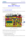
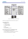
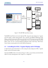
2.2 Block Diagram of the DE2-70 Board
Figure 2.2 gives the block diagram of the DE2-70 board. To provide maximum flexibility for the
user, all connections are made through the Cyclone II FPGA device. Thus, the user can configure
the FPGA to implement any system design.