


DE2-70 User Manual
74
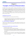
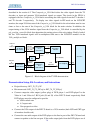
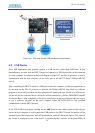
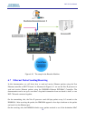
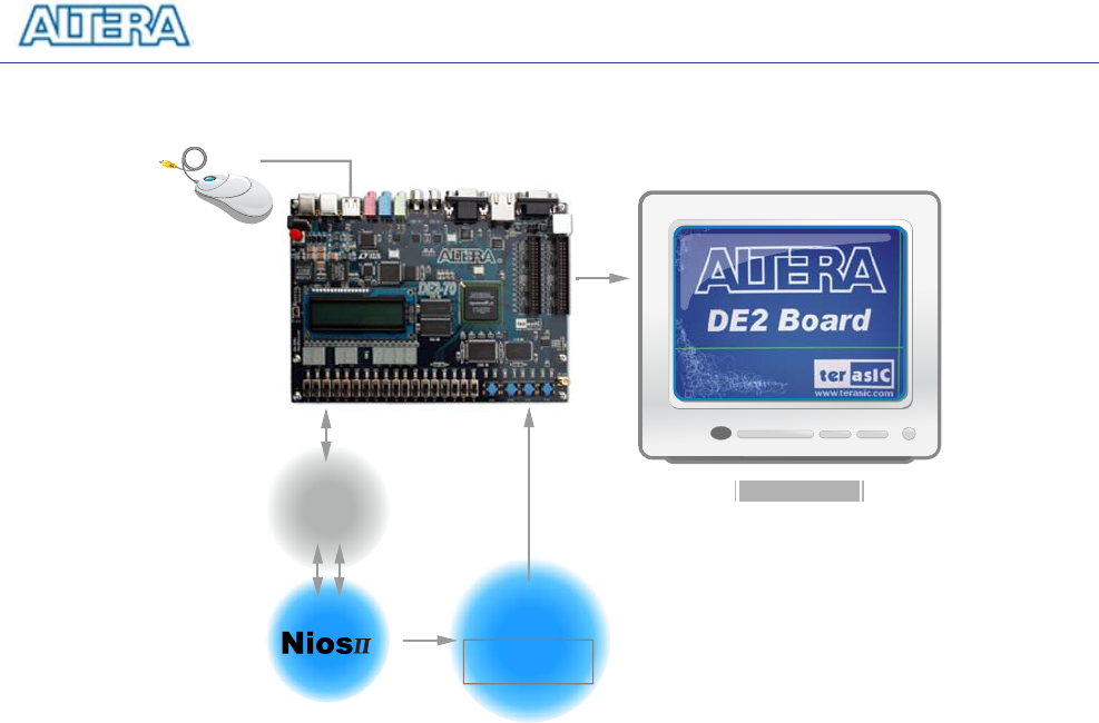
USB
Driver
VGA
Controller IP
On-Chip Video
Frame Buffer
VGA Monitor
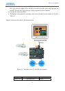
Figure 6.6. The setup for the USB paintbrush demonstration.
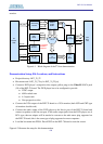
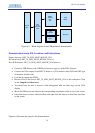
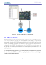
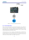
6.5 USB Device
Most USB applications and products operate as USB devices, rather than USB hosts. In this
demonstration, we show how the DE2-70 board can operate as a USB device that can be connected
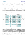
to a host computer. As indicated in the block diagram in Figure 6.7, the Nios II processor is used to
communicate with the host computer via the host port on the DE2-70 board’s Philips ISP1362
device.
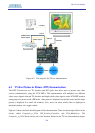
After connecting the DE2-70 board to a USB port on the host computer, a software program has to
be executed on the Nios II processor to initialize the Philips ISP1362 chip. Once the software
program is successfully executed, the host computer will identify the new device in its USB device
list and ask for the associated driver; the device will be identified as a Philips PDIUSBD12 SMART
Evaluation Board. After completion of the driver installation on the host computer, the next step is
to run a software program on the host computer called ISP1362DcUsb.exe; this program
communicates with the DE2-70 board.
In the ISP1362DcUsb program, clicking on the Add button in the window panel of the software
causes the host computer to send a particular USB packet to the DE2-70 board; the packet will be
received by the Nios II processor and will increment the value of a hardware counter. The value of
the counter is displayed on one of the board’s 7-segment displays, and also on the green LEDs. If