


DE2-70 User Manual
68
monitor.
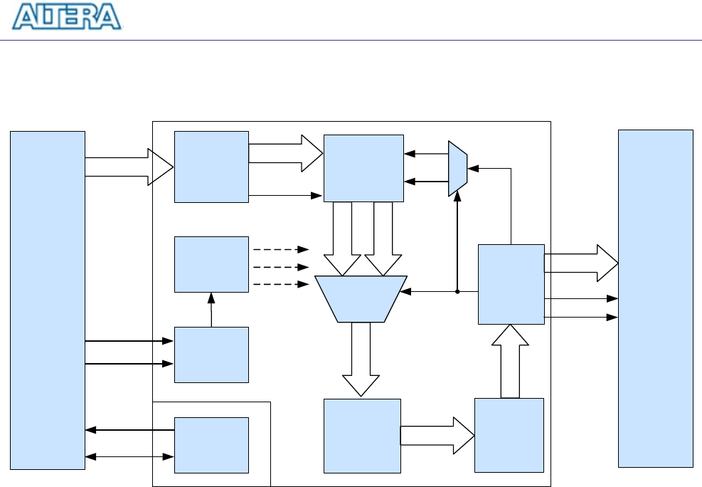
ITU-R 656
Decoder
YCbCr
To
RGB
VGA
Controller
Even 4:2:2
Odd 4:2:2
MUX
YUV 4:2:2
Odd
Request
10-bit RGB
I2C_SCLK
I2C_SDAT
Data Valid
DLY0
DLY1
DLY2
TD_DATA
TD_HS
TD_VS
To Control the
Initiation
Sequence
TV
Decoder
7180
Initiation
Delay
Timer
Locked
Detector
I2C_AV
Config
SDRAM
Frame
Buffer
YUV 4:2:2
To
YUV 4:4:4
YUV 4:2:2
VGA
DAC
7123
RGB
VGA_HS
VGA_VS
YUV 4:2:2
VGA_Y
Even
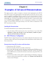
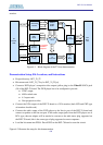
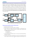
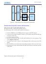
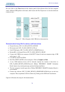
Figure 6.1. Block diagram of the TV box demonstration.
Demonstration Setup, File Locations, and Instructions
• Project directory: DE2_70_TV
• Bit stream used: DE2_70_TV.sof or DE2_70_TV.pof
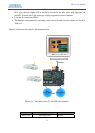
• Connect a DVD player’s composite video output (yellow plug) to the Video-IN 1 RCA jack
(J8) of the DE2-70 board. The DVD player has to be configured to provide
o NTSC output
o 60 Hz refresh rate
o 4:3 aspect ratio
o Non-progressive video
• Connect the VGA output of the DE2-70 board to a VGA monitor (both LCD and CRT type
of monitors should work)
• Connect the audio output of the DVD player to the line-in port of the DE2-70 board and
connect a speaker to the line-out port. If the audio output jacks from the DVD player are of
RCA type, then an adaptor will be needed to convert to the mini-stereo plug supported on
the DE2-70 board; this is the same type of plug supported on most computers
• Load the bit stream into FPGA. Press KEY0 on the DE2-70 board to reset the circuit
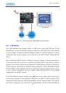
Figure 6.2 illustrates the setup for this demonstration.