


DE2-70 User Manual
4
Chapter 2
Altera DE2-70 Board
This chapter presents the features and design characteristics of the DE2-70 board.
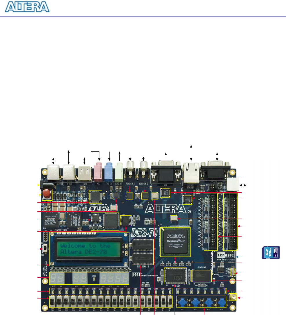
2.1 Layout and Components
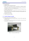
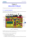
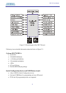
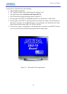
A photograph of the DE2-70 board is shown in Figure 2.1. It depicts the layout of the board and
indicates the location of the connectors and key components.
TV Decoder (NTSC/PAL)
50Mhz Oscillator
Expansion Header 2
SMA Extemal Clock
IrDA Transceiver
8Mbyte Flash Memory
8 Green LEDs
18 Toggle Switches
7-Segment Displays
16x2 LCD Module
Altera USB Blaster
Controller chipset
Altera EPCS16
Configuration Device
USB Host/Slave
Controller
Audio CODEC
Power ON/OFF Switch
12V DC Power Supply
Connector
RUN/PROG Switch for
JTAG/AS Modes
18 Red LEDs
Expansion Header 1
Altera Cyclone II
FPGA with 70K LEs
VGA 10-bit DAC
28Mhz Oscillator 2Mbyte SSRAM32Mbyte SDRAMx2 4 Push-button Switches
Ethernet 10/100M Controller
TV Decoder (NTSC/PAL) X2
PS2 Port
RS-232 Port
Ethernet 10/100M Port
USB Host Port
USB Device Port
USB Blaster Port
VGA Out
Video In 2Video In 1
Line In
Mic in Line Out
Lock
SD Card Slot
(SD Card Not Included)
Figure 2.1. The DE2-70 board.
The DE2-70 board has many features that allow the user to implement a wide range of designed
circuits, from simple circuits to various multimedia projects.
The following hardware is provided on the DE2-70 board:
• Altera Cyclone
®
II 2C70 FPGA device
• Altera Serial Configuration device - EPCS16
• USB Blaster (on board) for programming and user API control; both JTAG and Active Serial